Miscellaneous Interfaces
PRELIMINARY INFORMATION
NVIDIA Jetson Orin NX DG-10931-001_v0.1 | 68
Table 12-11. CAN Signal Connections
Module Pin Name Type Termination Description
CAN_TX O CAN Transmit: Connect to matching pin of device
CAN_RX I CAN Receive: Connect to Peripheral pin of device
12.5 Fan
Jetson Orin NX provides PWM and Tachometer functionality for controlling a fan as part of the
thermal solution. Information on the PWM and Tachometer pins and functions can be found in
the following locations:
Jetson Orin NX Pin Mux
• This is used to configure GPIO14 (PWM) for FAN_PWM and GPIO08 for FAN_TACH. The pin
used for
FAN_PWM is configured as GP_PWM6. The pin used for FAN_TACH is configured
as a GPIO.
Orin (SoC) Technical Reference Manual (TRM)
• Functional descriptions and related registers can be found in the TRM for the FAN_PWM
(PWM chapter).
Table 12-12. Jetson Orin NX Fan Pin Descriptions
Pin #
Module Pin
Name Orin Signal Usage and Description
Recommended
Usage Direction Pin Type
230 GPIO14 GP31_PWM3 Fan PWM Fan Output (note) CMOS – 1.8V
208 GPIO08 GP62 Fan tachometer Fan Input (note) CMOS – 1.8V
Notes:
1. In the Direction column, Output is from Jetson Orin NX. Input is to Jetson Orin NX. Bidir is for Bidirectional signals.
2. The direction indicated for GPIO014 and GPIO08 is associated with their use as Fan PWM/Tach. The pins support GPIO
functionality, so support both input and output operation (bidirectional).
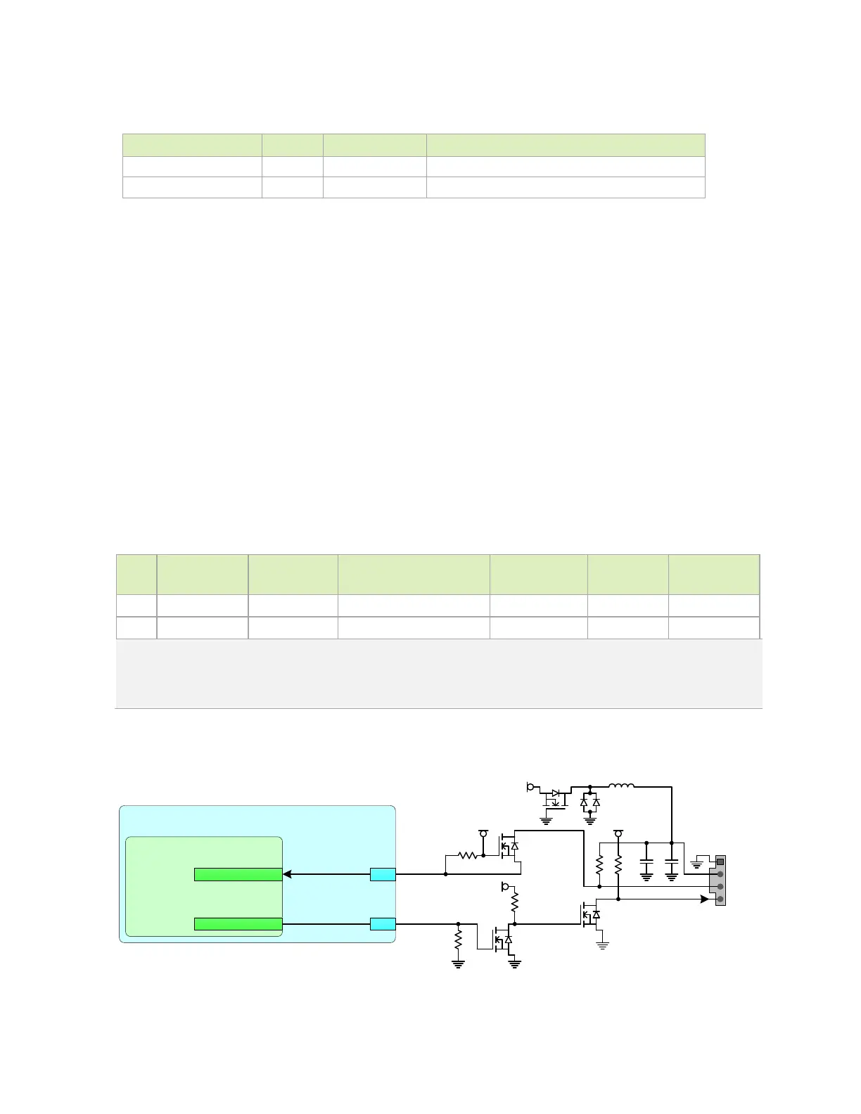
Figure 12-7. Jetson Orin NX Fan Connections
VDD_5V_IN
G
S
D
1
2
3
4
G
S
D
1kΩ
10 kΩ
10uF
Fan
Header
Jetson
SoC – Fan
GP3 1_ PWM3
FAN_TACH
FAN_PWM
GP6 2
230
208
10 0k Ω
GP IO 08
GP IO 14
VDD_5V_IN
G
S
D
10 kΩ
10 kΩ
VDD_1V8
G
S D
0.1uF
BAT54 C
SM23 09
PSAC-TRG
DMN2 6
DO UFB4
DMN2 6
DO UFB4
DMN2 6
DO UFB4
10 0u H
VDD_5V_IN

 Loading...