1021
3. Instructions
CS/CJ/NSJ Series Instructions Reference Manual (W474)
Failure Diagnosis Instructions
3
FAL
1. The specified error code will be written to A400.
2. The error code and the time that the error occurred will be written to the Error Log Area (A100
through A199).
3. The appropriate Auxiliary Area Flags are set based on the error code and error details.
4. The ERR Indicator on the CPU Unit will flash and PLC operation will continue.
5. The non-fatal error message for the specified system error will be displayed on the Programming
Console.
Note 1 FAL(006) can be used to generate non-fatal errors from the system when debugging the program. For
example, a system error can be generated intentionally to check whether or not error messages are being
displayed properly at an interface such as a Programmable Terminal (PT).
2 The value of A529 (the system-generated FAL/FALS number) is a dummy FAL number (FAL, FALS, and
FPD numbers are shared.) used when a non-fatal error is generated intentionally by the system. This num-
ber is a dummy FAL number, so it does not change the status of the Executed FAL Number Flags
(A360.01 to A391.15) or the error code.
When it is necessary to generate two or more system errors (fatal and/or non-fatal errors), different errors
can be generated by executing the FAL/FALS/FPD instructions more than once with the same values in
A529 and N, but different values in S and S+1.
3 If a more serious error (including a system-generated fatal error or FALS(007) error) occurs at the same
time as the FAL(006) instruction, the more serious error’s error code will be written to A400.
4 To clear a system error generated by FAL(006), turn the PLC OFF and then ON again. The PLC can be
kept ON, but the same processing will be required to clear the error as if the specified error had actually
occurred.
Refer to the CS/CJ Series Operation Manual or the CJ2 CPU Unit Hardware Operation Manual (W472).
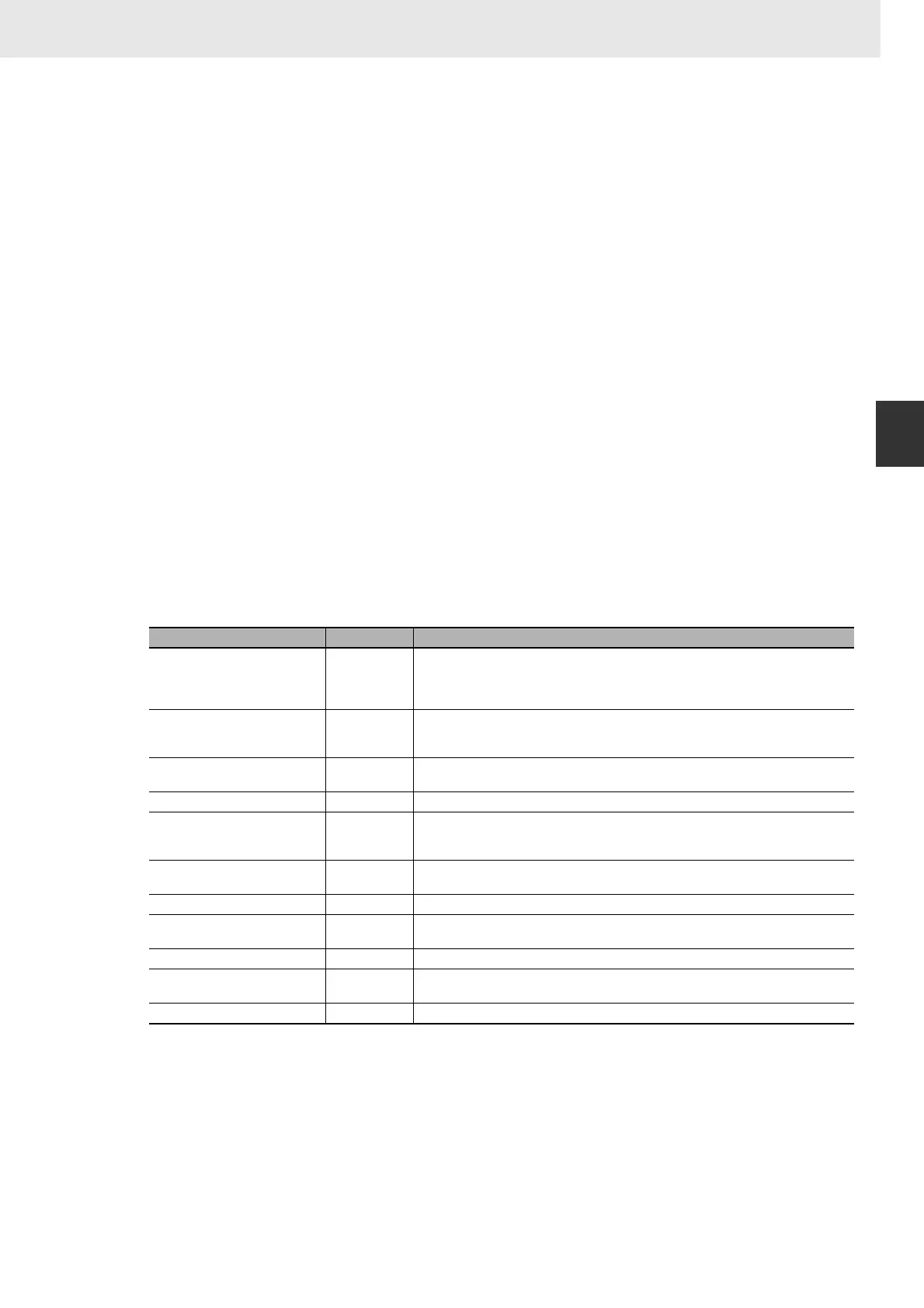
The following table shows how to specify error codes and error details in S and S+1.
Error name S S+1
Interrupt Task Error 008B hex • Bit 15 OFF: Interrupt task error
Bits 00 to 14: Task number of interrupt task where error occurred.
• Bit 15 ON: Interrupt task execution conflicted with Special I/O Unit refreshing
Bits 00 to 14: Unit number of Special I/O Unit with refreshing conflict
Basic I/O Error 009A hex Rack location of Unit where error occurred
• Bits 08 to 15: Rack number (binary) of Rack where the affected Unit is mounted
• Bits 00 to 07: Slot number (binary) of slot where the affected Unit is mounted
PLC Setup Error 009B hex PLC Setup Error Location
0000 to FFFF hex
I/O Table Verification Error 00E7 hex --- (not fixed)
Non-fatal Inner Board Error 02F0 hex Inner Board Error Information
• Bits 00 to 03: Invalid
• Bits 04 to 15: Error defined by the Inner Board
CPU Bus Unit Error 0200 hex CPU Bus Unit’s unit number:
0000 to 000F hex
Special I/O Unit Error 0300 hex Special I/O Unit’s unit number:0000 to 005F hex or 00FF hex (unit number undetermined)
SYSMAC BUS Error 00A0 hex SYSMAC BUS Master Unit’s unit number:
0000 or 0001 hex
Battery Error 00F7 hex --- (not fixed)
CPU Bus Unit Setup Error 0400 hex CPU Bus Unit’s unit number:
0000 to 000F hex
Special I/O Unit Setup Error 0500 hex Special I/O Unit’s unit number:0000 to 005F hex
 Loading...


