System Status Setting Window Section 3-7
61
Note Refer to 3-5 Creating a New PLC for the operation in the [Register PLC Unit]
window.
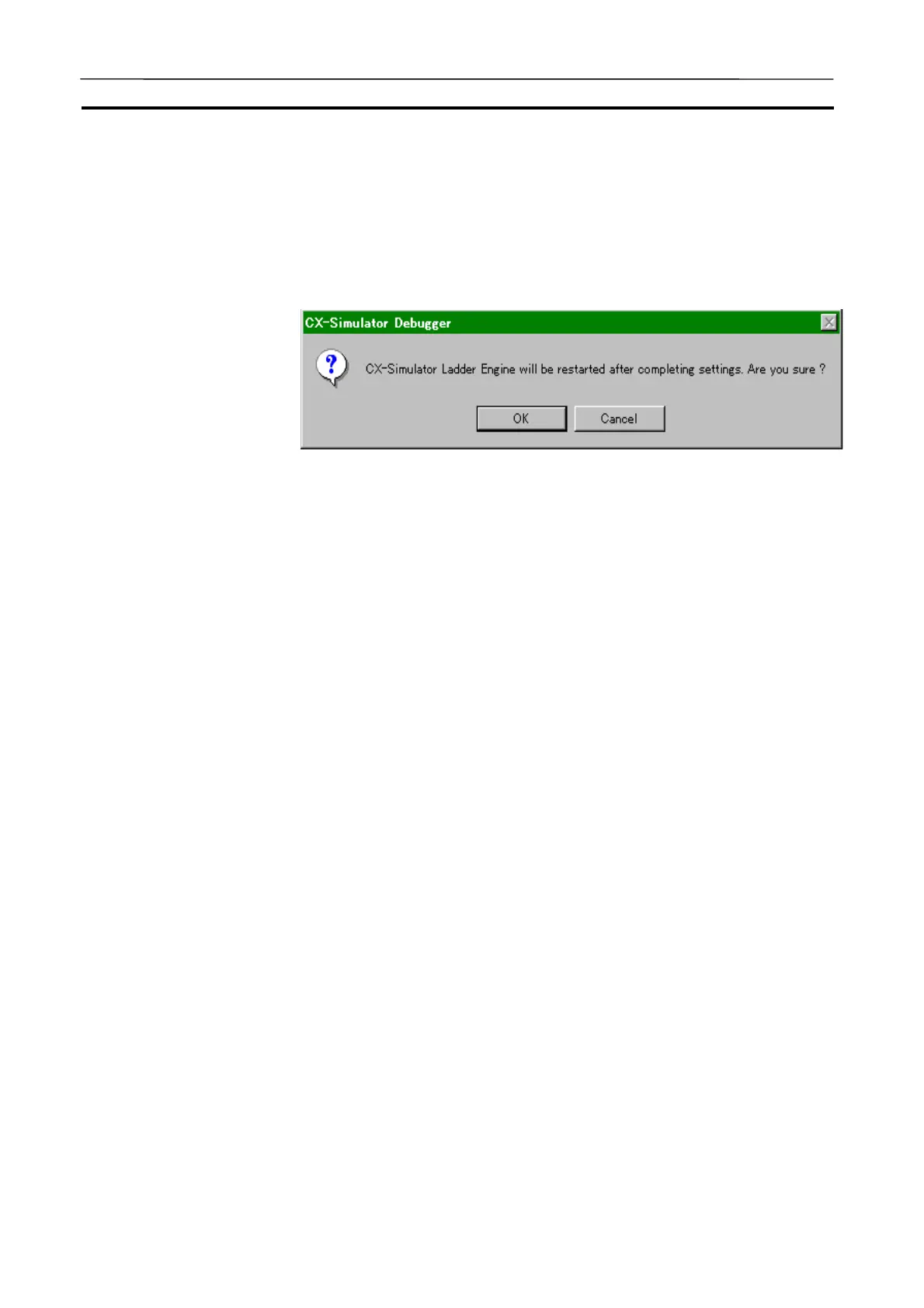
2. Click the [OK] button when the unit registration is completed. Changing
the Unit configuration will display the Restart message of the Ladder En-
gine.
3. Click the [OK] button to restart. Clicking the [Cancel] button will return to
the [Register PLC Unit] window.
Note Restarting the Ladder Engine will clear the I/O memory areas according to the
PLC Setup and read the Autoexec file automatically.
3-7-4 UM Settings
The [UM Settings] window allows to set for the UM to store a ladder diagram.
Unlike an actual PLC, the CX-Simulator has two program areas: (1) the pro-
gram area for applications (UM1) where the ladder diagram to be simulated is
stored and (2) the one for debugging (UM2) where the ladder diagram gener-
ating virtual external outputs.
AUDIN - 8, avenue de la malle - 51370 Saint Brice Courcelles - Tel : 03.26.04.20.21 - Fax : 03.26.04.28.20 - Web : http: www.audin.fr - Email : info@audin.fr

 Loading...


