58
Converting from Previous Models Section 2-11
■ Manipulating the Rotary Switches for the Node Address with a Precision
Screwdriver
Converting from ETN11 Mode to ETN21 Mode
1. Turn OFF the power to the PLC, and set the Ethernet Unit's rotary switches
for the node address as follows:
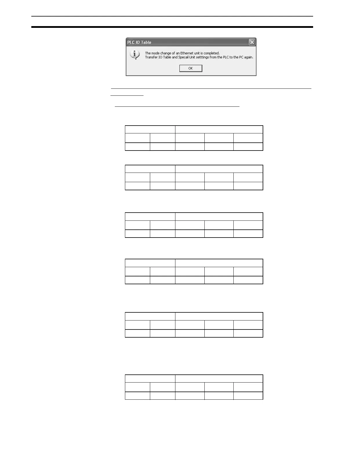
2. Turn ON the power to the PLC. The Unit's indicators will change as follows:
3. Set the rotary switches for the node address to 01. There will be no change
to the indicators.
4. Set the rotary switches for the node address to F1. The RUN indicator will
begin to flash.
5. Set the rotary switches for the node address to 01. The Unit mode change
function will start, and the ERH indicator will flash for approximately five
seconds.
6. After the mode has been changed, the indicators will appear as shown be-
low, depending on whether the change was completed normally or if an er-
ror occurred.
• If the Mode Change was Completed Normally
Node address Indicators
×16
1
×6
0
RUN ERC ERH
0 0 Not lit Not lit Not lit
Node address Indicators
×16
1
×16
0
RUN ERC ERH
0 0 Not lit Lit Not lit
Node address Indicators
×6
1
×16
0
RUN ERC ERH
0 1 Not lit Lit Not lit
Node address Indicators
×16
1
×16
0
RUN ERC ERH
F 1 Flashing Lit Not lit
Node address Indicators
×16
1
×16
0
RUN ERC ERH
0 1 Flashing Lit Flashing
Node address Indicators
×16
1
×16
0
RUN ERC ERH
0 1 Flashing Lit Lit

 Loading...


