152
Overview of Direct Connection Operations
Section 5-1
5-1 Overview of Direct Connection Operations
This section explains allocated bits and words, control of the NT20S and PC notifi-
cation methods, and the actual procedures used for switching screens, thereby
providing the basic information required to use the NT20S-ST121-EV3 host link/
NT link and NT20S-ST122-V1 (C200H direct communication).
5-1-1 Equipment and Settings Used in This Section
The following equipment and settings are used in the examples in this section:
[Equipment] PT : NT20S-ST121-EV3
PC : CQM1
Support tool : NT-series Support Tool Ver. 2.j
[Support tool settings]
PT type : NT20S
Memory capacity : 96 KB
Direct setting : Ver.5
Direct Macn Type : OMRON
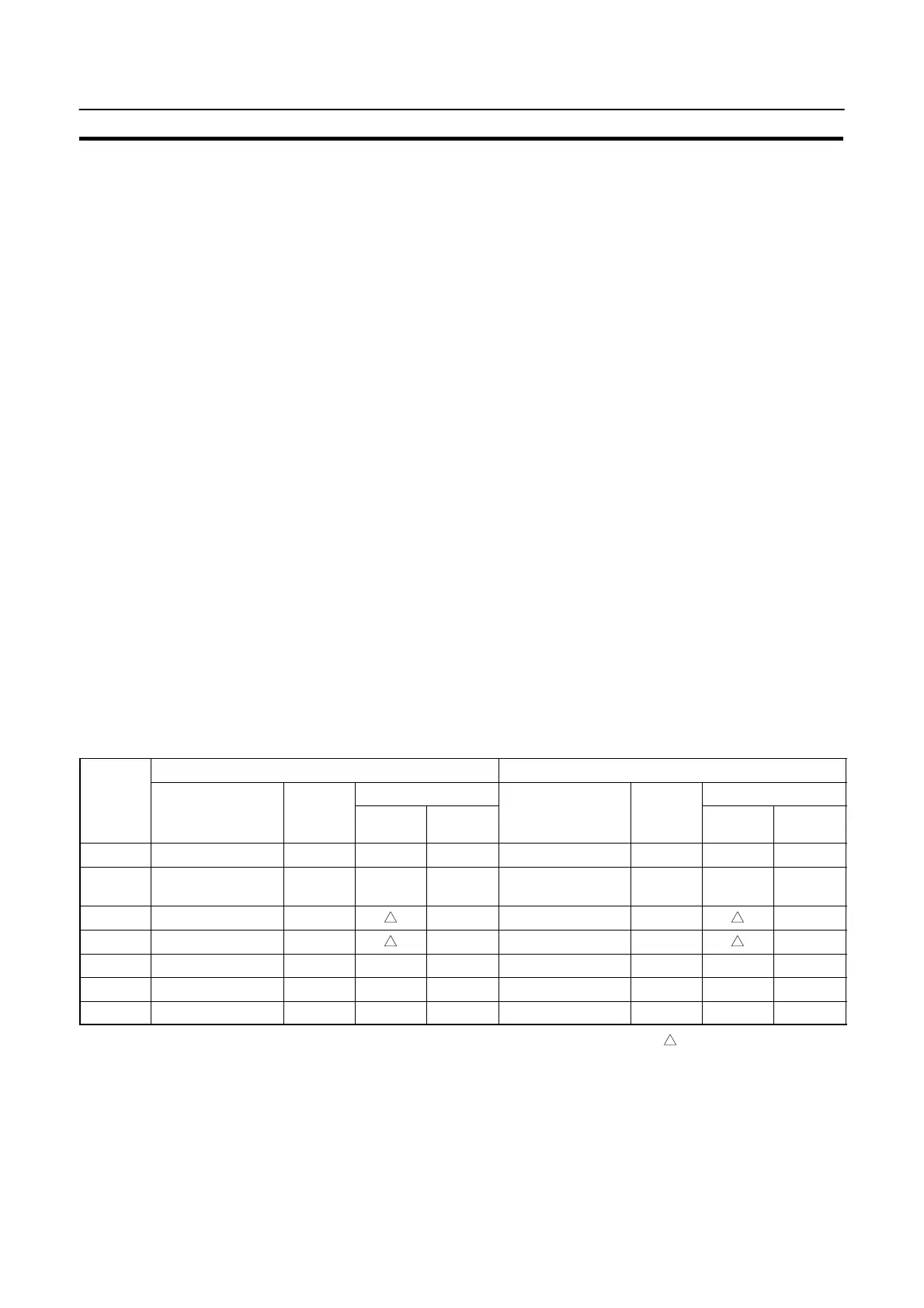
5-1-2 Allocatable Bits and Words
When the host link/NT link is used, the following bits and words are allocated to the
PC and used for the NT20S operation. The range of respective area varies with the
type of PC. Refer to Appendix L PC Memory Map (page 278).
The allocations must be made without exceeding respective area range.
[OMRON PCs]
C Series PCs CVM1/CV Series PCs
S
mbol
Allocated Word
Allocated Word
Area Name
oca
e
Bit
Numeral
Character
String
Area Name
oca
e
Bit
Numeral
Character
String
DM Data Memory f f f Data Memory f f f
CH
Internal/Special
Relay
f f f
Internal/Special
Relay
f f f
TIM Timer Timer
CNT Counter Counter
HR Holding Relay f f f –
AR Auxiliary Relay f f f Auxiliary Relay f f
LR Link Relay f f f –
f: OK : 1 word only : NG
When allocating a memory table to words, the allocation must not exceed the word
area.
Since the special auxiliary relays of the CV series PCs are allocated to the system,
they cannot be used for purposes other than the system use. However, reading
from them is possible.

 Loading...


