64
Host Connections by RS-232C
Section 2-8
Connector
Signal direction
pin #
Signal name Abbreviation
NT20S ← → Host
2 Send data SD (TXD) →
3 Receive data RD (RXD) ←
4 Request to send RS (RTS) →
5 Clear to send CS (CTS) ←
6 +5 V output, max. 150 mA +5V →
9 Signal ground SG (GND) —
Unlisted pins are not used.
Note: For cable parts and the wiring method, refer to APPENDIX G Method for Making
the Cable for Connection to the Host (page 256).
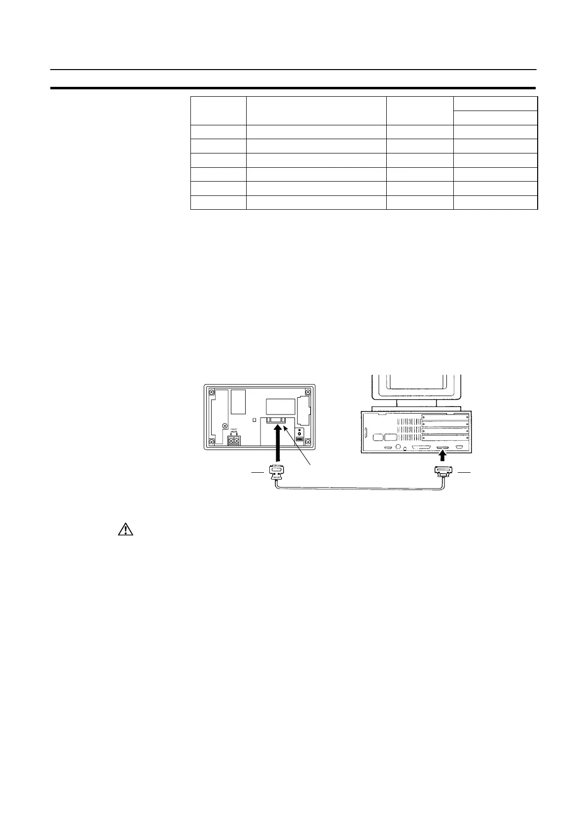
Connecting to the Host Computer
Use a cable that is compatible with the RS-232C connector of the host to connect
the NT20S and the host (see the example in the figure below).
In the example shown here, the cable connects the 9-pin connector of the NT20S
and 25-pin connector of the host. If the host has a 9-pin RS-232C connector, use
an RS-232C cable with 9-pin connectors at both ends.
NT20S
25-pin connector
Host Interface connector
(RS-232C, 9-pin type)
9-pin connector
RS-232C cable
Caution: S When making the connection, switch off the power to the NT20S and PC before
disconnecting or connecting any connector.
S After connecting the communication cable, always secure it with the screws.
Otherwise the cable may disconnect, causing operation to fail.
Note: If using the +5 V supply of pin No.6, check first that the equipment that is to receive
the supply has a current capacity no greater than 150 mA. The +5 V output of the
NT20S is +5 V DC "5%, max. 150 mA.

 Loading...


