3-32
3-1 Servo Drive Specifications
OMNUC G5-SERIES AC SERVOMOTOR AND SERVO DRIVE USER'S MANUAL
3
Specifications
Control Input Details
Details on the input pins for the CN1 connector are described here.
High-speed Photocoupler Input
Pin 3: +Reverse pulse (+CW), +feed pulse (+PULS), or +phase A (+FA)
Pin 4: −Reverse pulse (−CW), −feed pulse (−PULS), or −phase A (−FA)
Pin 5: +Forward pulse (+CCW), +direction signal (+SIGN), or +phase B (+FB)
Pin 6: −Forward pulse (−CCW), −direction signal (−SIGN), or −phase B (−FB)
Function
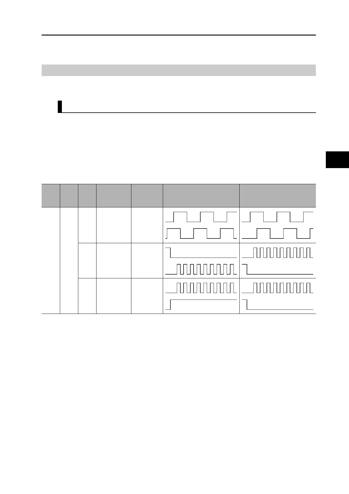
The functions of these signals depend on the settings of the Command Pulse Rotation Direction
Switching Selection (Pn006) and the Command Pulse Mode Selection (Pn007).
Note 1. If the Command Pulse Rotation Direction Switching Selection (Pn006) is set to 1, the rotation direction will be
reversed.
Note 2. If the photocoupler LED is turned ON, each signal will go high as shown above.
Pn005
Set
value
Pn006
Set
value
Pn007
Set
value
Command
pulse mode
Input pins Motor forward command Motor reverse command
00
0/2
90° phase
difference
signals
(quadruple
multiplier)
3: +FA
4: −FA
5: +FB
6: −FB
1
Reverse
pulse/forward
pulse
3: +CW
4: −CW
5: +CCW
6: −CCW
3
Feed pulse/
direction
signal
3: +PULS
4: −PULS
5: +SIGN
6: −SIGN
L
 Loading...


