5-7
5-2 Speed Control
OMNUC G5-SERIES AC SERVOMOTOR AND SERVO DRIVE USER'S MANUAL
5
Basic Control Mode
5-2 Speed Control
Outline of Operation
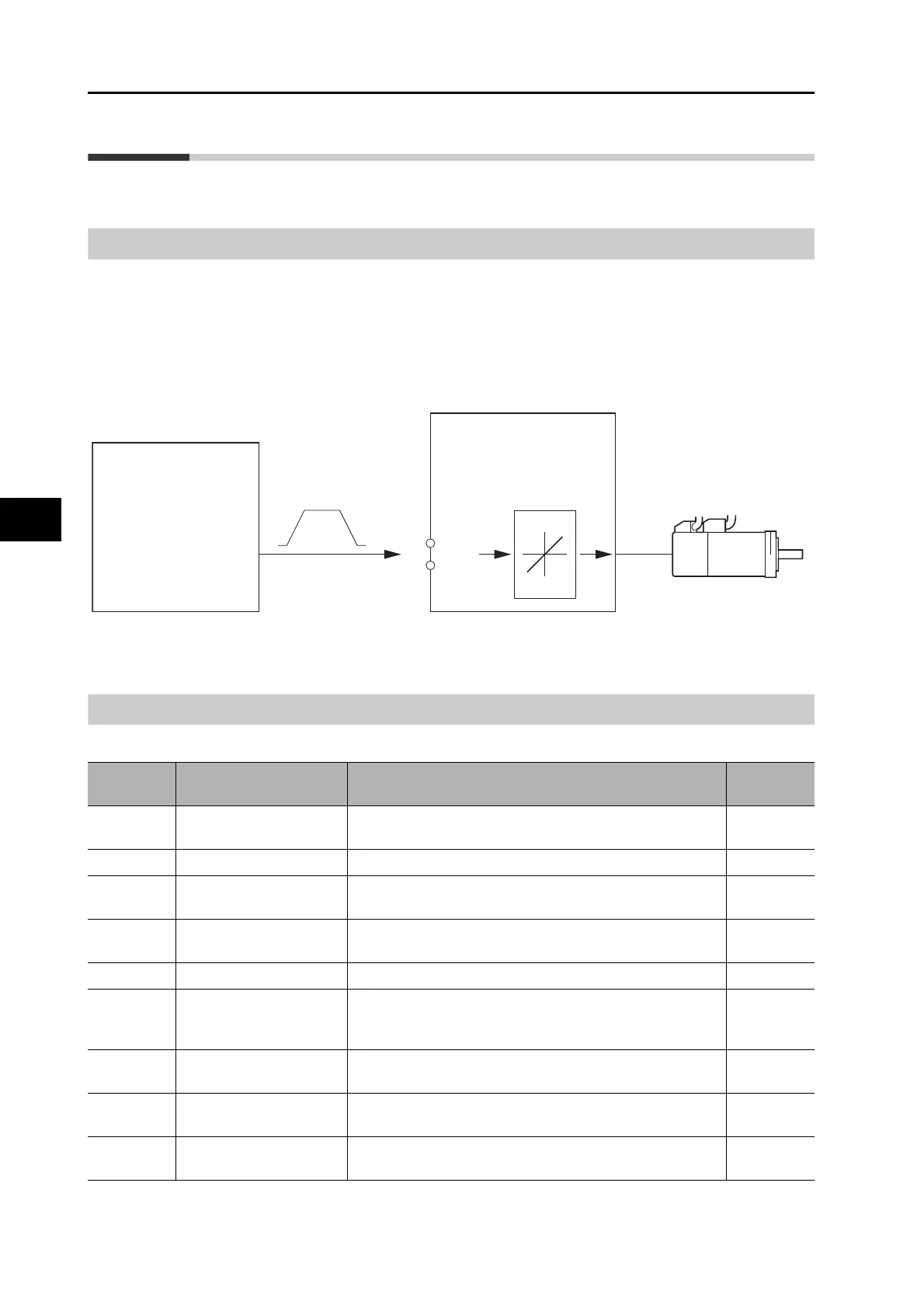
Motor speed control is performed based on the analog voltage input from the controller.
You can also perform position control by combining with a controller that has a position control
function.
You can change the relation between the speed command and the rotation speed by setting the
Speed Command Scale (Pn302).
Parameters Requiring Settings
Drive
OMNUC G5
Motor
OMNUC G5
Controller
(analog voltage output type)
Motion Control Unit
CS1W-MC221/421(−V1)
REF
AGND
14
15
Speed Command Scale
(Pn302)
Speed Control Mode
Analog voltage
(speed command)
V
r/min
Parameter
number
Parameter name Explanation Reference
Pn000 Reference direction
Select the relation between the reference command and the
rotation direction in the motor.
P.8-2
Pn001 Control Mode Selection Select the control mode. P.8-2
Pn300
Command Speed
Selection
Select the speed command input method.
P.8-25
Pn301
Speed Command
Direction Selection
Set the method for designating the forward or reverse
direction for the speed command.
P.8-25
Pn302 Speed Command Scale Set the input gain for the analog speed command input. P.8-27
Pn303
Analog Speed Command
Rotation Direction
Switching
Inverts the polarity of the analogue speed command.
P.8-27
Pn312
Soft Start Acceleration
Time
Set the acceleration time for internally set speed control. Set
the time until 1,000 r/min is reached.
P.8-28
Pn313
Soft Start Deceleration
Time
Set the deceleration time for internally set speed control. Set
the time until 1,000 r/min is reached.
P.8-29
Pn314
S-curve Acceleration/
Deceleration Time Setting
Set the S-curve time in the time width centered on the
inflection points for acceleration and deceleration.
P.8-29
 Loading...


