3-59
3-3 Servomotor Specifications
OMNUC G5-SERIES AC SERVOMOTOR AND SERVO DRIVE USER'S MANUAL
3
Specifications
3-3 Servomotor Specifications
The following OMNUC G5-Series AC Servomotors are available.
3,000-r/min Servomotors
2,000-r/min Servomotors
1,500-r/min Servomotors
1,000-r/min Servomotors
There are various options available, such as models with brakes, or different shaft types.
Select a Servomotor based on the mechanical system's load conditions and the installation
environment.
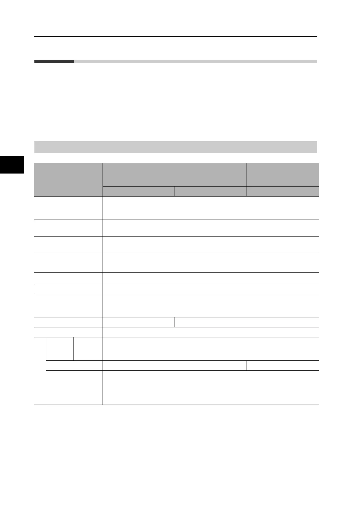
General Specifications
*1. The amplitude may be amplified by machine resonance. Do not exceed 80% of the specified value for extended periods of time.
*2. 24.5m/s
2
is specified for 1,500-r/min Servomotors of 7.5 to 15 kW and 1,000-r/min Servomotors of 4.5 to 6 kW.
*3. UL 1004-6 applies only to 1,500-r/min Servomotors of 7.5 to 15 kW and 1,000-r/min Servomotors of 4.5 to 6 kW.
Note 1. Do not use the cable when it is laying in oil or water.
Note 2. Do not expose the cable outlet or connections to stress due to bending or the weight of the cable itself.
Note 3. Disconnect all connections to the Servomotor before attempting a megameter test (insulation resistance
measurement) on a Servomotor. Failure to follow this guideline may result in damaging the Servomotor.
Never perform a dielectric strength test on the Servomotor. Failure to follow this guideline may result in
damaging the internal elements.
Item
3,000-r/min Servomotors
1,000-r/min Servomotors
1,500-r/min Servomotors
2,000-r/min Servomotors
50 to 750 W 1 to 5 kW 900 W to 15 kW
Ambient operating
temperature and operating
humidity
0 to +40°C, 20% to 85% (with no condensation)
Storage ambient
temperature and humidity
−20 to +65°C, 20% to 85% (with no condensation)
Maximum allowable temperature: 80°C for 72 hours maximum (standard humidity)
Operating and storage
atmosphere
No corrosive gases
Vibration resistance *
1
Acceleration of 49 m/s
2
*2
24.5 m/s
2
max. in X, Y, and Z directions when the motor is stopped
Impact resistance
Acceleration of 98 m/s
2
max. 3 times each in X, Y, and Z directions
Insulation resistance Between power terminal and FG terminal: 20 MΩ min. (at 500 VDC)
Dielectric strength 1,500 VAC between power terminal and FG terminal for 1 min (voltage 100 V, 200 V)
1,800 VAC between power terminal and FG terminal for 1 min (voltage 400 V)
1,000 VAC between brake terminal and FG terminal for 1 min
Insulation class Type B Type F
Protective structure IP67 (except for through-shaft parts and motor and encoder connector pins)
EC
Directive
Low
Voltage
Directive
EN60034
-1/-5
UL standards UL1004-1 UL1004-1, UL1004-6
*3
CSA standards CSA C22.2 No. 100
 Loading...


