4-33
4-3 Wiring Conforming to EMC Directives
OMNUC G5-SERIES AC SERVOMOTOR AND SERVO DRIVE USER'S MANUAL
4
System Design
4-3
Wiring Conforming to EMC Directives
Conformance to the EMC Directives (EN 55011 Class A Group 1 (EMI) and EN 61000-6-2
(EMS)) can be ensured by wiring under the conditions described in this section.
These conditions are for conformance of OMNUC G5-series products to the EMC directives.
EMC-related performance of these products, however, may be influenced by the configuration,
wiring, and other conditions of the equipment in which the products are installed. The EMC
conformance of the system as a whole must be confirmed by the customer.
The following are the requirements for EMC Directive conformance.
The Servo Drive must be installed in a metal case (control panel). (The motor does not, however,
have to be covered with a metal plate.)
Noise filters and lightening surge absorptive elements (surge absorbers) must be installed on power supply lines.
Braided shielded cables must be used for all encoder cables. (Use tin-plated, mild steel wires for
the shielding.)
All cables, I/O wiring, and power lines connected to the Servo Drive must have clamp cores
installed to improve the noise immunity.
The shields of all cables must be directly connected to a ground plate.
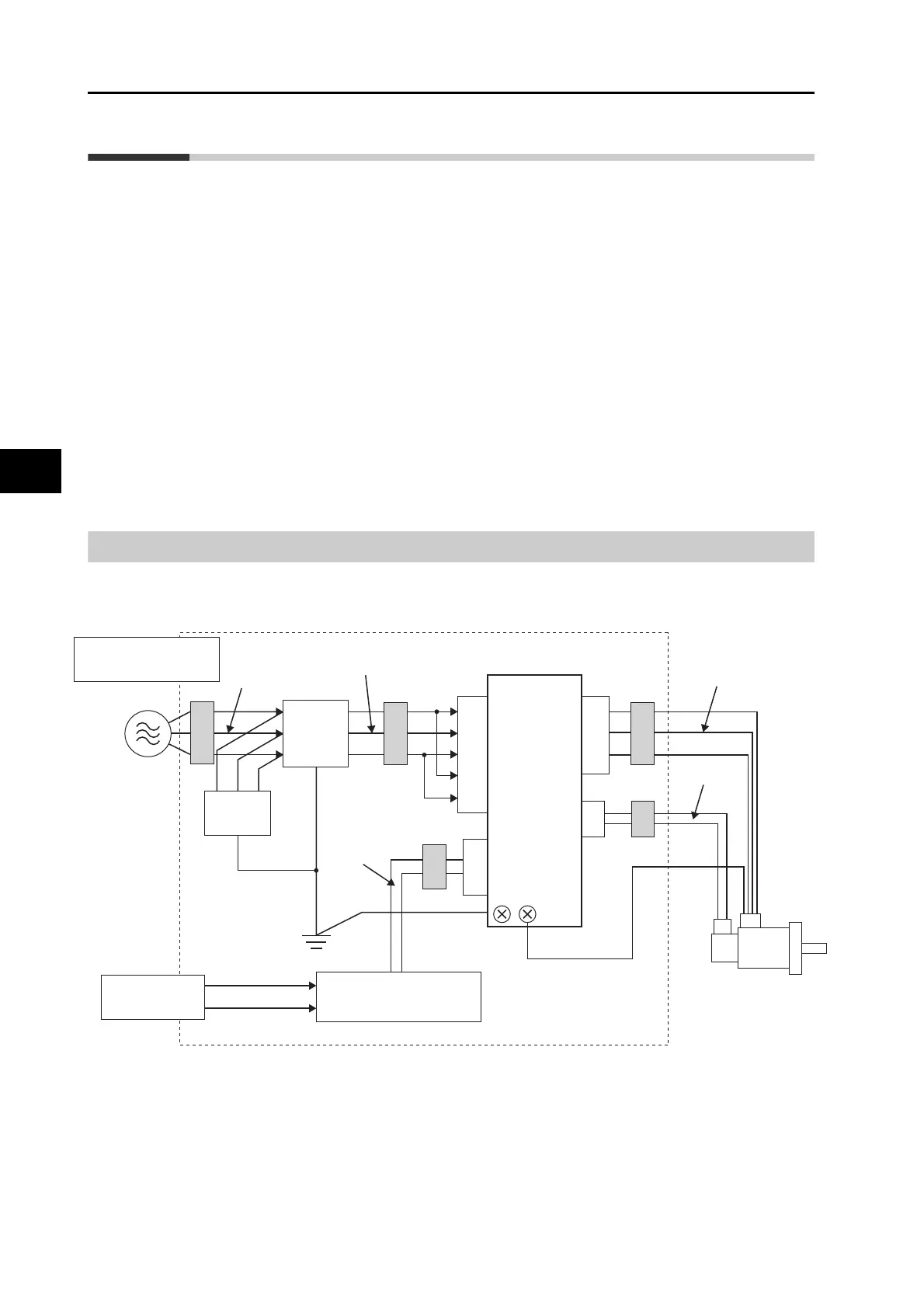
Wiring Method
R88D-KTA5L/-KT01L/-KT02L/-KT04L/-KT01H/-KT02H/-KT04H/-KT08H/-KT10H/-
KT15H/-KT20H/-KT30H/-KT50H/-KT75H/-KT150H
*1.
For models with a single-phase power supply input (R88D-KTA5L/-KT01L/-KT02L/-KT04L/-KT01H/-
KT02H/-KT04H/-KT08H/-KT10H/-KT15H), the main circuit power supply input terminals are L1 and L3.
Ground the motor's frame to the machine ground when the motor is on a movable shaft.
Use a ground plate for the frame ground for each unit, as shown in the above diagrams, and ground to a single point.
Use ground lines with a minimum thickness of 3.5 mm
2
, and arrange the wiring so that the ground
lines are as short as possible.
A no-fuse breaker, surge absorber, and noise filter should be positioned near the input terminal
block (ground plate), and I/O lines should be separated and wired at the shortest distance.
Controller
(1)
(2)
(6)
(5)
(7)
(8)
L1
L2
L3
L1C
L2C
SG
NF
FC1 FC3
SD
FC1
FC1
CNA
CN1
CNB
CN2
U
V
W
SM
Single-phase
:
100 VAC
Single-phase: 100 VAC
2/3-phase: 200 VAC
(3)
(4)
FC2
 Loading...


