5-50
5-10 User Parameters
5
Operating Functions
This parameter can be used to reverse the logic of the encoder pulses output from the Servo Drive.
Phase Z is synchronized with phase A. The logic of phase Z cannot be reversed.
Explanation of Settings
Set the pulse rate for command pulses and Servomotor travel distance along with Pn4A and Pn4B.
For details, refer to Electronic Gear on page 5-9.
Pn45
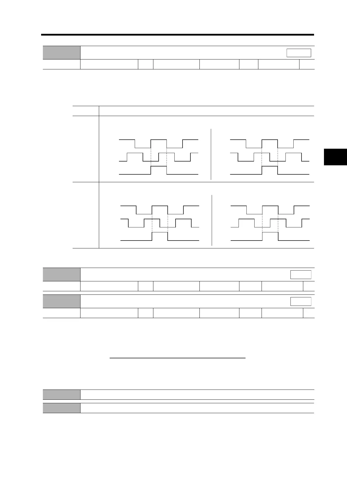
Encoder Output Direction Switch
Setting range 0 or 1 Unit --- Default setting 0
Power OFF → ON
Yes
All modes
Setting Explanation
0
Positive logic
1
Negative logic
Forward Rotation
Reverse Rotation
Phase A
Phase A
Phase B
Phase Z
Phase B
Phase Z
Forward Rotation
Reverse Rotation
Phase A
Phase B
Phase Z
Phase A
Phase B
Phase Z
Pn46
Electronic Gear Ratio Numerator 1
Setting range 1 to 10000 Unit --- Default setting 10000
Power OFF → ON
---
Pn47
Electronic Gear Ratio Numerator 2
Setting range 1 to 10000 Unit --- Default setting 10000
Power OFF → ON
---
Position
Position
Electronic Gear Ratio Denominator
Pn4B
x 2
Electronic Gear Ratio Numerator Exponent (Pn4A)
Electronic Gear Ratio Numerator 1 (Pn46)
or
Electronic Gear Ratio Numerator 2 (Pn47)
Pn48 Not used. (Do not change setting.)
Pn49 Not used. (Do not change setting.)
 Loading...


