Chapter 2
2-56
Standard Models and Specifications
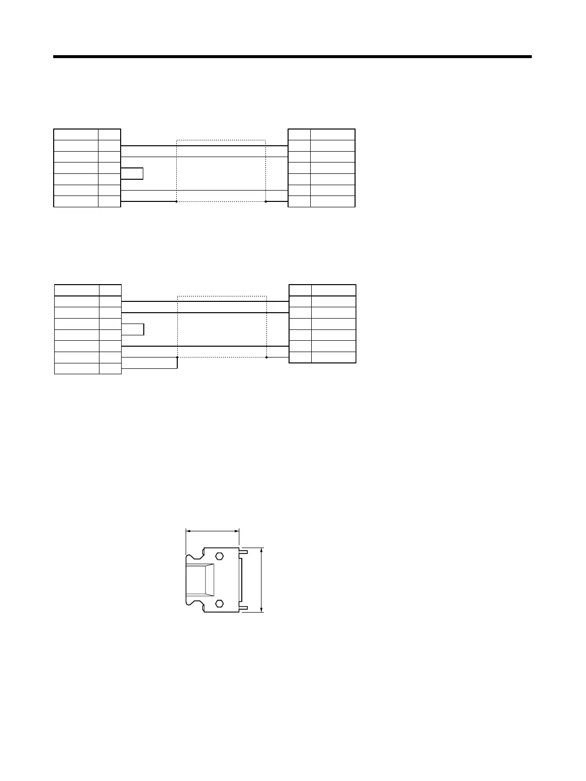
● Wiring
For DOS Personal Computers:
For NEC PC98 Notebook Computers
■ Control I/O Connector (R88A-CNU01C)
This is the connector for connecting to the Servo Driver’s Control I/O Connector (CN1). This connec-
tor is used when the cable is prepared by the user.
● External Dimensions
Computer
Symbol
Connector:
17JE-13090-02 (D8A) (DDK Ltd.)
Gray/Black
Orange/Black
Orange/Red
Cable: AWG28 × 3C UL2464
Servo Driver
Shell
No. No.
21
2
8
3
7
8
5
RXD
RXDTXD
TXD
RTS
CTS
GND
FG
GND
FG
Symbol
Case
Connector: HR212-10P-8P (Hirose Electric)
Computer
Symbol
Symbol
Gray/Black
Orange/Black
Orange/Red
Cable: AWG28 × 3C UL2464
Servo Driver
Shell
Connector plug:
10114-3000VE (Sumitomo 3M)
Connector case:
10314-52F0-008 (Sumitomo 3M)
No. No.
11
2
8
9
10
4
14
12
RXD
RXDTXD
TXD
RTS
CTS
GND
FG
FG
GND
FG
Case
Connector: HR212-10P-8P (Hirose Electric)
Connector plug:
10136-3000VE (Sumitomo 3M)
Connector case:
10336-52A0-008 (Sumitomo 3M)
43.6
39
t=18
 Loading...


