Chapter 2
2-70
Standard Models and Specifications
The following screwdriver can be used to release wires.
Recommended Screwdriver
■
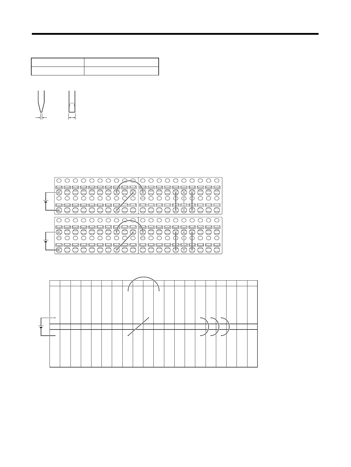
Servo Relay Unit Wiring Example
I/O power is supplied from terminals 20-0, 21-1, and 60-40 when a Servo Relay Unit is used. As
shown in the following example, wiring can be performed by simply connecting the signals.
Upper Terminal Block Pin Arrangement
Model Manufacturer
SZF1 Phoenix Contact
Side view Front vie
0.6 mm 3.5 mm
60
Upper terminal block
Lower terminal bloc
0
79
19
0 1 2 3 4 5 6 7 8 9
0 1 2 3 4 5 6 7 8 9
0 1 2 3 4 5 6 7 8 9
0 1 2 3 4 5 6 7 8 9
0 1 2 3 4 5 6 7 8 9
0 1 2 3 4 5 6 7 8 9
0 1 2 3 4 5 6 7 8 9
0 1 2 3 4 5 6 7 8 9
5 V
24 V
5 V
Latch signal input 1
Latch signal input 2
CNT1 A phase LD
+ input
CNT1 B phase LD
+ input
Servo Driver #1
Z phase LD+ output
---
Servo Driver #1 ALM
---
IN4
IN5
IN6
IN7
---
Servo Driver #1 RUN
Servo Driver #1
RESET
Servo Driver #1
ECRST
---
TXD+
RXD+
60 61 62 63
Latch signal 1
common (0 V)
Latch signal 2
common (0 V)
CNT1 A phase
LD-/-0 V
CNT1 B phase
LD-/0 V
Servo Driver #1
Z phase LD-/0 V
---
Common (0 V)
Servo Driver #1 INP
Common (0 V)
Common (0 V)
Common (0 V)
Common (0 V)
---
TXD-
RXD-
OUT0
OUT1
OUT2
OUT3
0 V
64 65 66 67 68 69 70 71 72 73 74 75 76 77 78 79
40 41 42 43 44 45 46 47 48 49 50 51 52 53 54 55 56 57 58 59
5 V
 Loading...


