93
Installing Serial Communications Units Section 3-2
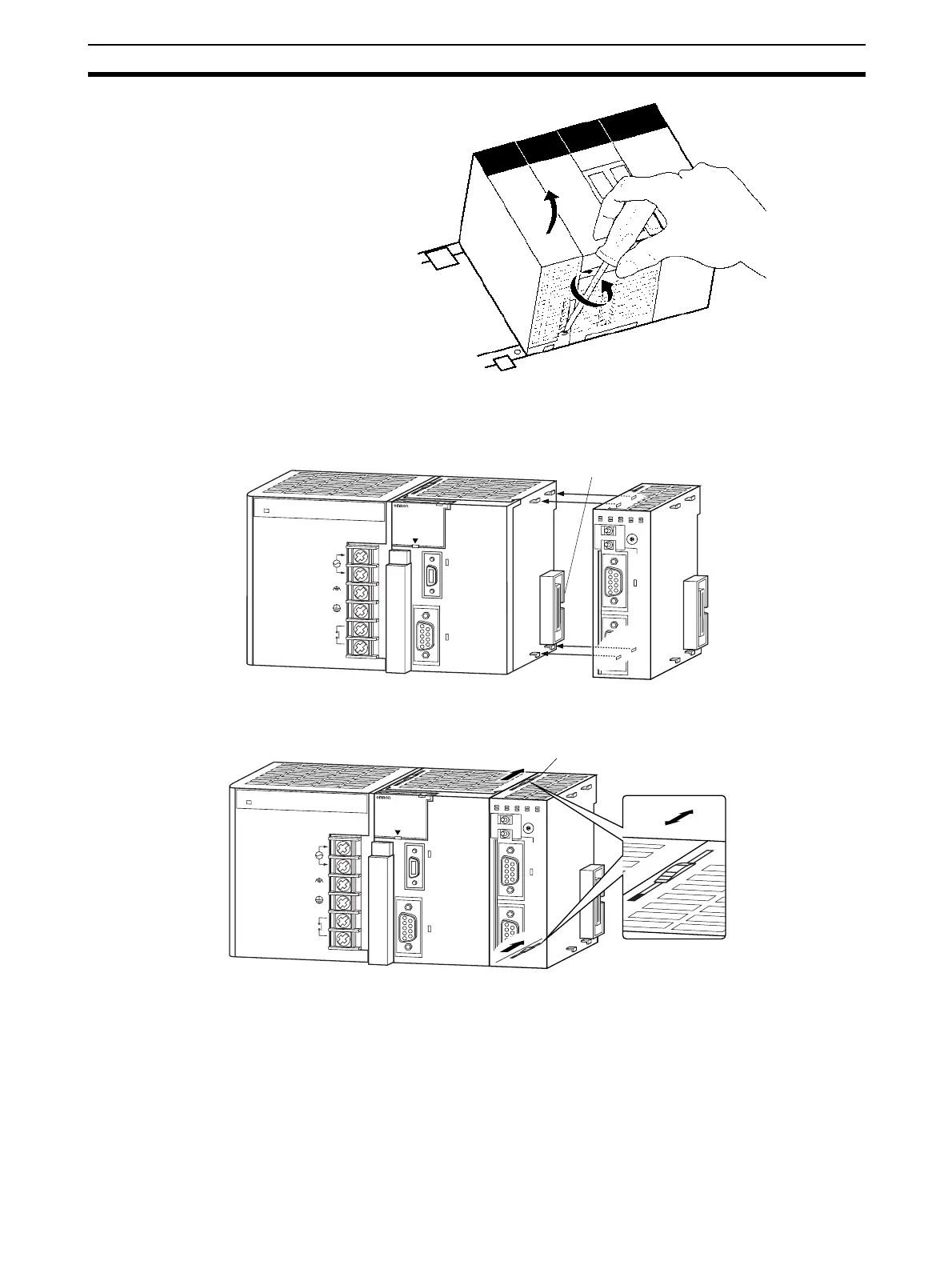
3-2-3 CJ-series Serial Communications Unit
1,2,3... 1. Align the connectors properly and then press in on the Unit to connect it.
2. Slide the sliders on the top and bottom of the Unit until they lock the Units
together.
Note If the sliders are not locked properly, the Serial Communications Units may
not function correctly.
To remove the Unit, move the sliders to the release position and then pull the
Units gently apart.
P
A
2
0
5
R
POWER
IN
P
U
T
A
C
1
0
0
-2
4
0
V
L2/N
L1
D
C
2
4
V
A
C
2
4
0
V
O
U
T
P
U
T
R
U
N
PERIPHERAL
ERR/ALM
RUN
INH
COMM
PRPHL
C
O
N
T
R
O
L
L
E
R
C
J
1
G
-C
P
U
4
4
S
Y
S
M
A
C
P
R
O
G
R
A
M
M
A
B
L
E
P
O
R
T
OPEN
B
U
S
Y
M
C
P
W
R
2
ON
4
TERM
RD2
SD2
RDY
NO.
UNIT
ERH
OFF
WIRE
0
1
2
3
4
5
6
7
8
9
A
B
C
D
E
F
ERC
RUN
SCU41
RD1
TER1
SD1
PORT1
(RS422
/485)
PORT2
Connector
P
A
2
0
5
R
POWER
IN
P
U
T
A
C
1
0
0
-2
4
0
V
L2/N
L1
D
C
2
4
V
A
C
2
4
0
V
O
U
T
P
U
T
R
U
N
PERIPHERAL
ERR/ALM
RUN
INH
COMM
PRPHL
C
O
N
T
R
O
L
L
E
R
C
J
1
G
-C
P
U
4
4
S
Y
S
M
A
C
P
R
O
G
R
A
M
M
A
B
L
E
PO
R
T
OPEN
B
U
S
Y
M
C
P
W
R
2
ON
4
TERM
RD2
SD2
RDY
NO.
UNIT
ERH
OFF
WIRE
0
1
2
3
4
5
6
7
8
9
A
B
C
D
E
F
ERC
RUN
SCU41
RD1
TER1
SD1
PORT1
(RS422
/485)
PORT2
Slider
Lock
Release

 Loading...


