97
Wiring Section 3-3
Note The signal names SDA/B and RDA/B do not always have the same polarity as
that shown above. Check the polarity of the external device before making
connections.
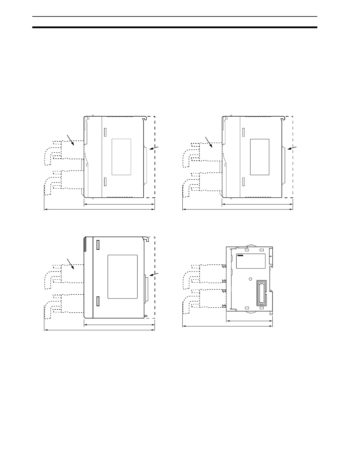
3-3-5 Mounting Height and Connector Cover Dimensions
When mounting the Serial Communications Board or Unit, make sure to pro-
vide space for the mounting height and connector cover dimensions shown
below.
Note The mounting heights shown above are applicable when the attached con-
nectors, connector covers, and recommended cables are used. The mounting
height may differ when other connectors, connector covers, and cables are
used. Determine the mounting height, taking into account the connectors,
connector covers, and the minimum bending radius of the cables.
3-3-6 Reducing Electrical Noise for External Wiring
Observe the following precautions for external wiring.
• When multi-conductor signal cable is being used, avoid using I/O wires
and other control wires in the same cable.
• If wiring racks are running in parallel, allow at least 300 mm between the
racks.
123
223
123
223
65
150
123
223
CS1W-SCB21-V1 Serial Communications Board
(mounted to CPU Unit)
Cable connector
CS1W-SCU21-V1/31-V1 Serial Communications Unit
Cable connector
Cable connector
CS1W-SCB41-V1 Serial Communications Board
(mounted to CPU Unit)
Backplane connector
Backplane connector
Backplane connector
Cable connector
CJ1W-SCU21-V1/31-V1/41-V1 Serial Communications Unit

 Loading...


