99
Wiring Section 3-3
3-3-8 NT-AL001-E Link Adapter Settings
The NT-AL001-E Link Adapter has a DIP switch for setting RS-422A/485 com-
munications conditions. When connecting the Unit or Board, refer to the DIP
switch settings shown in the following table.
Note When connecting to a CS/CJ-series CPU Unit, turn OFF pin 5 and
turn ON pin 6.
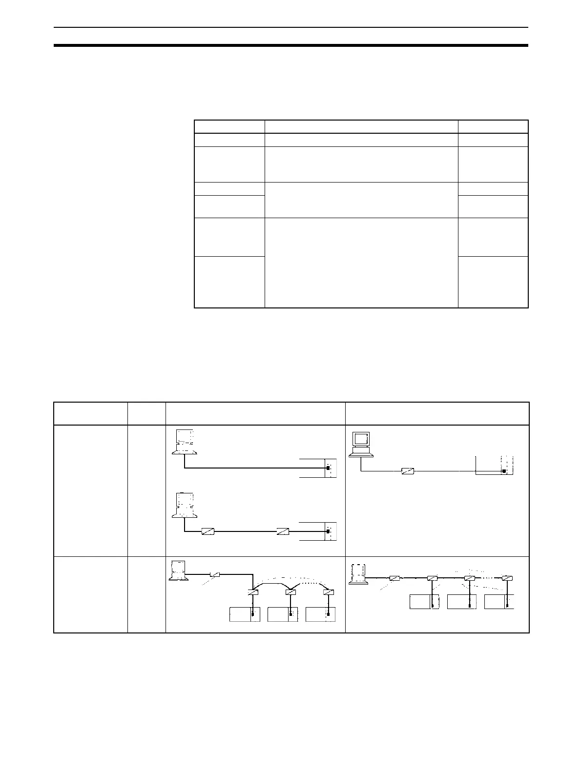
3-3-9 Connections for Host Link Communications
Port connections for Host Link communications are shown in the following
table. Up to 32 Units and Boards can be connected for 1:N connections.
Note 1. Four-wire connections must be used for RS-422A/485 connections with
Host Link communications.
2. “Resistance ON” indicates the terminating resistance must be turned ON.
3. “5-V power” indicates that a 5-V power supply is required for the Link
Adapter. Refer to the Link Adapter manual for details. A 5-V power supply
Pin Function Factory setting
1 Not used. Always set this pin to ON. ON
2 Built-in terminating resistance setting
ON: Connects terminating resistance.
OFF: Disconnects terminating resistance.
ON
3 2/4-wire setting
2-wire: Set both pins to ON.
4-wire: Set both pins to OFF.
OFF
4OFF
5 Transmission mode ()
Constant transmission: Set both pins to OFF.
Transmission performed when CTS signal in
RS-232C interface is at high level: Set pin 5 to
OFF and pin 6 to ON.
Transmission performed when CTS signal in
RS-232C interface is at low level: Set pin 5 to
ON and pin 6 to OFF.
ON
6OFF
Port Config-
uration
Schematic diagram, RS-232C ports Schematic diagram, RS-422A/485 ports
RS-232C
Computer to
PLC: C-mode or
FINS commands
PLC to com-
puter: FINS com-
mands
1:1
RS-232C
Computer to
PLC: C-mode or
FINS commands
1:N
NT-AL001-E
RS-232C
RS-232C
RS-422A/485
5-V power
Resistance ON
NT-AL001-E
RS-232C
Resistance ON
Resistance ON
NT-AL001-E
RS-232C
RS-422A/485
5-V power
Resistance ON
Resistance ON
NT-AL001-E
RS-232C
RS-232C
RS-422A/485
5-V power
Resistance ON
NT-AL001-E
RS-232C
RS-232C
Resistance ON
NT-AL001-E
RS-232C
RS-422A/485
5-V power
Resistance ON
B500-AL001
RS-422A
/485

 Loading...


