274
Modbus-RTU Slave System Section 9-1
9-1 Modbus-RTU Slave System
A Modbus-RTU Slave System can be used to send Modbus-RTU commands
from a host computer (e.g., personal computer) to a PLC to read and write I/O
memory.
Host-initiated
Communications
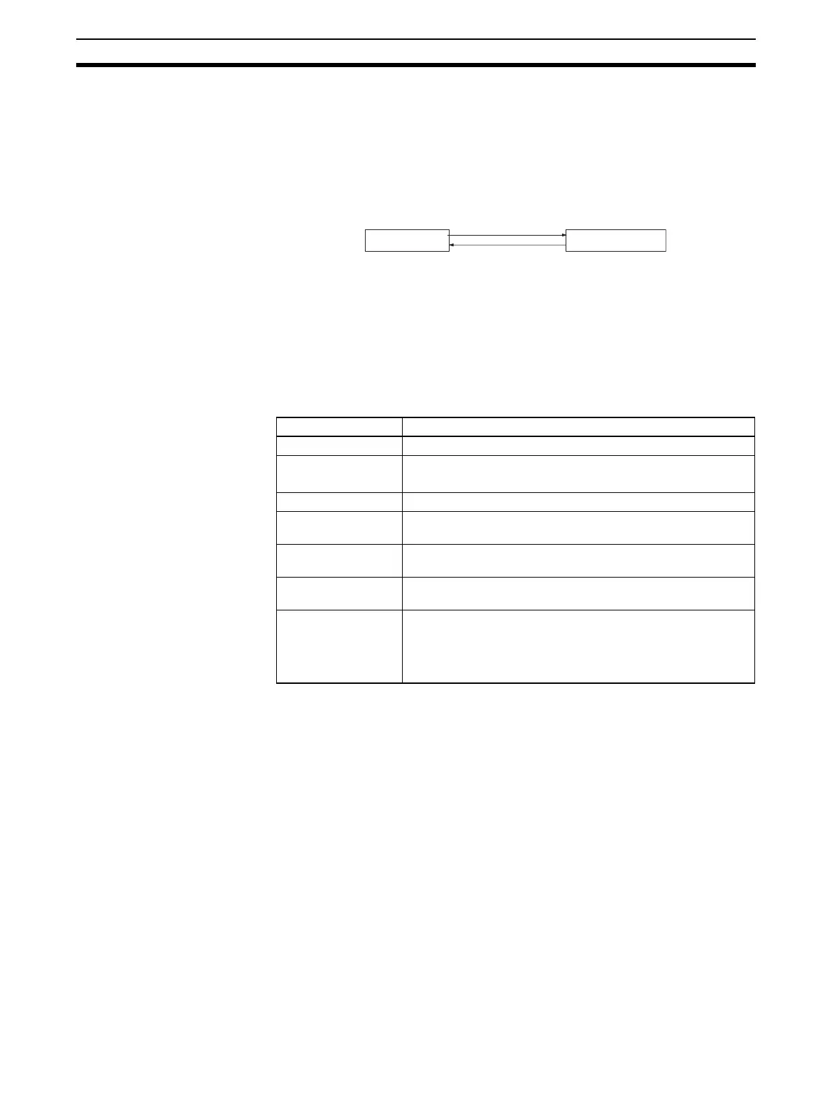
Communications in a Modbus-RTU Slave System are started by the host
computer.
The host computer sends a command to the PLC. The PLC processes the
command and returns a response to the host computer. This process is
repeated, allowing the host computer to monitor and control PLC operation.
Note Only Modbus-RTU slave mode is supported. A Modbus-ASCII slave mode is
not supported by the Serial Communications Boards or Serial Communica-
tions Units.
Modbus-RTU Specifications
Note 1. Modbus-ASCII mode is not supported.
2. The data length is fixed at 8 bits and cannot be changed by the user.
3. The number of stop bits is automatically determined by the parity and can-
not be set by the user.
4. The address cannot be set to 0. In commands, 0 is used to indicate broad-
cast commands.
9-1-1 Communicating with CS/CJ-series CPU Units Using Modbus
There are four data models that are defined for Modbus. Settings in the DM
Area are used to the I/O memory area in the CS/CJ-series CPU Unit corre-
sponding to each of these data models for use by the Serial Communications
Board/Unit. The I/O memory areas that can be set for each of the Modbus
data models are given below.
1. Discrete inputs: CIO Area (fixed)
2. Coils: CIO, Work, Holding, or Auxiliary Area
3. Input Registers: CIO, Work, Holding, or Auxiliary Area
4. Holding Registers: DM or EM Area
Host computer
CS/CJ-series PLC
Command
Response
Item Description
Mode Modbus-RTU slave mode (See note 1.)
Baud rate 1,200/2,400/4,800/9,600/19,200/38,400/57,600/115,200 bps
Default: 19,200 bps
Data length 8 bits (See note 2.)
Parity Odd, even, or none
Default: Even
Stop bits Odd or even parity:1 bit
No parity: 2 bits (See note 3.)
Address setting
range
1 to 247 (broadcasting: 0) (See note 4.)
Frame format Slave address: 1 byte
Function code: 1 byte
Data: 0 to 252 bytes
CRC code: 2 bytes

 Loading...


