114
RS-232C and RS-422A/485 Wiring Section 3-4
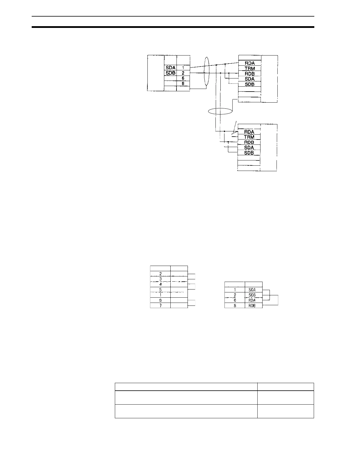
1:N, 2-wire Connections from RS-422A/485 to RS-422A/485 Ports
Communications Mode: 1:N NT Link
Note 1. Serial Communications Board/Unit settings:
Terminating resistance ON, 2-wire.
2. The terminating resistant setting shown above is an example for the
NT631/NT631C. The setting method varies with the PT. Refer to the man-
ual for you PT for details.
3-3-12 Connections in Loopback Test
Connect the communications ports as shown below.
3-4 RS-232C and RS-422A/485 Wiring
3-4-1 Recommended RS-232C Wiring Examples
It is recommended that RS-232C cables be connected as described below
especially when the Serial Communications Board or Unit is used in an envi-
ronment where it is likely to be subject to electrical noise.
1,2,3... 1. Always use shielded twisted-pair cables as communications cables.
Serial Communications
Board/Unit
Pin
Signal
Signal
PT
Terminal block
FG
Hood
D-sub, 9-pin
connector (male)
RS-422A
/485 In
terface
Short bar
Signal
PT
Terminal block
FG
RS-422A
/485 In-
terface
-
(See note 2.)
RS-422A/
485 Inter-
face
RS-422A/485 port
Pin Signal
Pin
Signal
SD
RD
RTS
CTS
FG
DTR
DSR
RS-232C port
Model Manufacturer
UL2464 AWG28x5P IFS-RVV-SB (UL product)
AWG28x5P IFVV-SB (non-UL product)
Fujikura Ltd.
UL2464-SB (MA) 5Px28AWG (7/0.127) (UL product) CO-
MA-VV-SB 5Px28AWG (7/0.127) (non-UL product)
Hitachi Cable, Ltd.

 Loading...


