106
Wiring Section 3-3
2. The terminating resistant setting shown above is an example for the
NT631/NT631C. The setting method varies with the PT. Refer to the man-
ual for you PT for details.
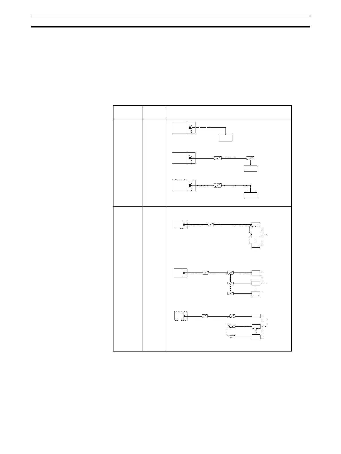
3-3-10 Connections for Protocol Macros, Serial Gateway, No-protocol
Mode, and Modbus-RTU Slave Mode
This section describes the connections for protocol macros, Serial Gateway,
and no-protocol communications. Up to 32 Boards or Units can be used for
1:N connections.
Port Configu-
ration
Schematic diagram
RS-232C 1:1
RS-232C 1:N
Resistance
ON
NT-AL001-E
Resistance ON
NT-AL001-E
RS-232C
RS-232C
interface
RS-232C
RS-422A/485
RS-232C
interface
NT-AL001-E
RS-232C
RS-422A/485
Resistance
ON
RS-422A/
485
interface
5-V power
NT-AL001-E
RS-232C
RS-232C
RS-422A/485
NT-AL001-E
RS-232C
RS-422A
/485
Resistance ON
B500-AL001-E
Resistance ON
Resistance
ON
Resistance ON
NT-AL001-E
NT-AL001-E
RS-232C
RS-232C
RS-232C
Resistance ON
5-V
ower
Resistance
ON
RS-422A/485
RS-422A/485
interface
RS-422A/485
interface
RS-232C
interface

 Loading...


