113
Wiring Section 3-3
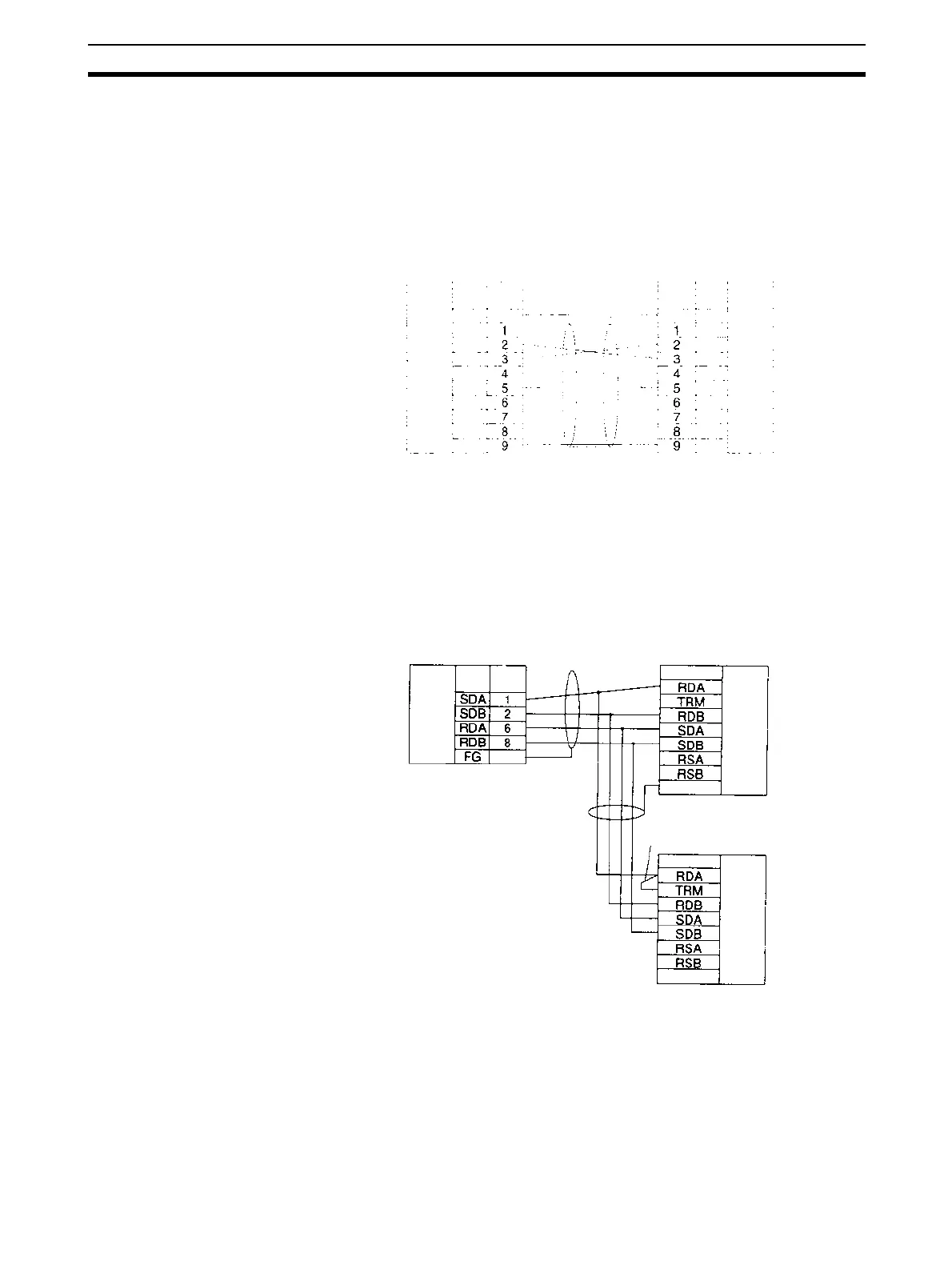
3-3-11 1:N NT Link Connections with Programmable Terminals
The connections used for each port type in NT Link mode are the same as for
protocol macro mode. Refer to
3-3-10 Connections for Protocol Macros,
Serial Gateway, No-protocol Mode, and Modbus-RTU Slave Mode
. Up to
eight Units or Boards can be used for a 1:N connection.
Direct Connections from RS-232C to RS-232C Ports
• Communications Mode: Host Link (unit number 0 only for Host Link)
NT Link (1:N, N = 1 Unit only)
• OMRON Cables with Connectors:
XW2Z-070T-1: 0.7 m
XW2Z-200T-1: 2 m
1:N, 4-wire Connections from RS-422A/485 to RS-422A/485 Ports
Communications Mode: 1:N NT Link
Note 1. Serial Communications Board/Unit settings:
Terminating resistance ON, 4-wire.
2. The terminating resistant setting shown above is an example for the
NT631/NT631C. The setting method varies with the PT. Refer to the man-
ual for you PT for details.
Serial Communications
Board or Unit
PinSignal
PT
D-sub, 9-pin
connector (male)
RS-232C
Interface
Hood
Hood
D-sub, 9-pin
connector (male)
RS-232C
Interface
Pin Signal
FG
FG
SD
RD
RTS
CTS
5V
DSR
DTR
SG
FG
--
SD
RD
RTS
CTS
5V
--
--
SG
Serial Communications
Board/Unit
Pin
Signal
Signal
PT
Terminal block or
D-sub connector
FG
Hood
D-sub, 9-pin
connector (male)
RS-422
A/485
Inter
face
Short bar
Signal
PT
Terminal block or
D-sub connector
FG
RS-422A
/485 In
terface
-
-
(See note 2.)
RS-422A/
485 Inter-
face

 Loading...


