238
Communications Frames Section 6-8
Further, to write the CompoWay/F command to the command storage area
using CMND(490) in frame order (without creating empty bytes), the SID com-
ponent of the CompoWay/F command requires 1 byte of ASCII as 30 hex, so
the subsequent components (s+3 and afterwards) must be set in one byte
each.
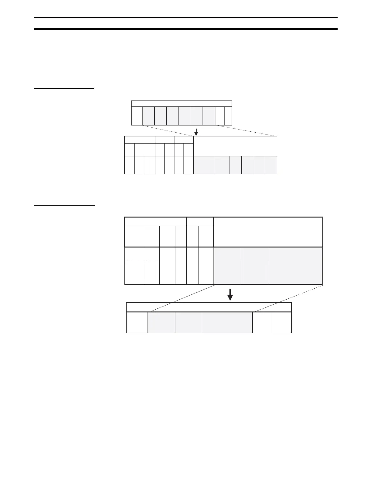
Response Frame
6-8-2 Modbus-RTU
Command Frame
Note The silent interval in the Modbus-RTU frame is automatically generated by the
Serial Communications Board/Unit.
Frame before Conversion
CompoWay/F
(See note.)
FINS end codeFINS commandFINS header
Frame after Conversion
CompoWay/F
STX
(02 hex)
Node No.
(× 10
1
)
(× 10
2
)
(ASCII
code
4 bytes)
Remote
network
address
(DNA)
Remote
node
address
(DA1)
SRCMRC MRES SRES
Serial
port
allocated
address
00 hex Serial
port unit
address
03
28
Node No.
(× 10
1
)
(× 10
2
)
(ASCII code
2 bytes)
Sub-
address
"00"
(ASCII code
3030 hex)
etc.
Command
(MRC,
SRC)
(ASCII
code
4 bytes)
End code
(ASCII
code
2 bytes)
Response
(MRES,
SRES)
(ASCII
code
4 bytes)
Text
(ASCII
code)
Sub-
address
"00"
(ASCII
code
3030
hex) etc.
Command
(MRC,
SRC)
(ASCII
code
8 bytes)
Text
(ASCII
code)
Response
(MRES,
SRES)
(ASCII
code
8 bytes)
ETX
(03 hex)
BCCEnd code
(ASCII
code
8 bytes)
Remote
unit ad-
dress
(DA2)
etc.
User-
speci-
fied
User-
speci-
fied
Frame before Conversion
FINS header
Frame after Conversion
FINS command
Remote
network
address
(DNA)
Remote
node
address
(DA1)
Remote
unit
address
(DA2)
Etc. MRC SRC
Serial port
allocated
address
00 hex Serial
port
unit
address
28 04
or local
network
address
or local
network
node
address
Modbus-RTU frame
Start (silent
interval of
3.5
characters)
(See note.)
Slave
address
(1 byte)
FUNCTION
code
(1 byte)
Communications data
(n bytes)
Error
check
CRC
(1 byte)
End (silent
interval of
3.5
characters)
(See note.)
Modbus-RTU
(command section only)
Slave
address
(1 byte)
FUNCTION
code(1 byte)
Communications data
(n bytes)

 Loading...


