101
Wiring Section 3-3
!Caution Do not use the 5-V power from pin 6 of the RS-232C port for anything but the
NT-AL001-E Link Adapter. Using this power supply for any other external
device may damage the Serial Communications Board/Unit or the external
device.
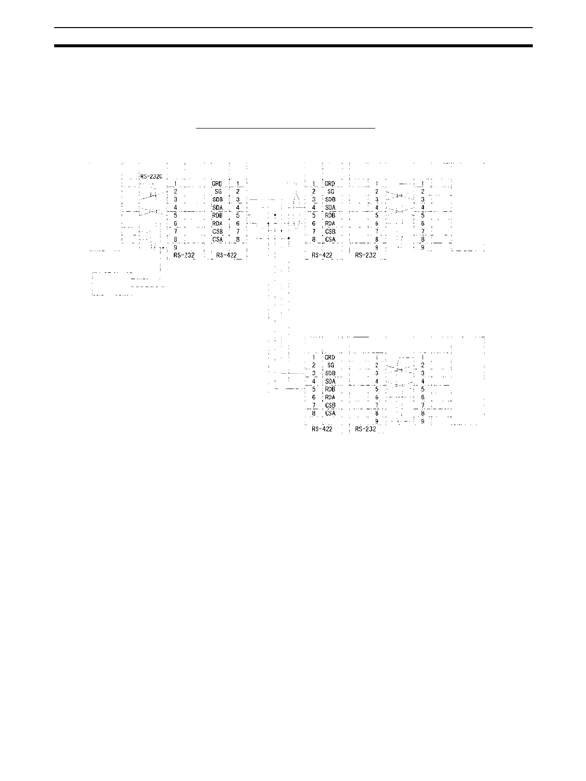
1:N Connections Using RS-232C Ports
Note We recommend using the following NT-AL001-E Link Adapter Connecting
Cables to connect to NT-AL001-E Link Adapters.
XW2Z-070T-1: 0.7 m
XW2Z-200T-1: 2 m
5-V (+)
power (-)
D-sub, 9-pin
connector (male)
NT-AL001-E Link Adapter
Shield
RS-232C
Interface
RS-232C
Interface
RS-232C
Interface
Signal
Pin
DIP Switch Settings
Pin 1: ON
Pin 2: ON
(terminating resistance)
Pin 3: OFF
Pin 4: OFF
Pin 5: OFF
Pin 6: OFF
NT-AL001-E Link Adapter
RS-232C
NT-AL001-E Link Adapter
Pin
Pin
Serial Communications
Board/Unit
Serial Communications
Board/Unit
Computer
(See note)
D-sub, 9-pin
connector (male)
DIP Switch Settings
Pin 1: ON
Pin 2: OFF
Pin 3: OFF
Pin 4: OFF
Pin 5: OFF
Pin 6: ON
DIP Switch Settings
Pin 1: ON
Pin 2: ON
(terminating resistance)
Pin 3: OFF
Pin 4: OFF
Pin 5: OFF
Pin 6: ON
D-sub, 9-pin
connector (male)
Terminal block
Signal Signal
RS-422A
Signal
Pin
Pin
Signal
Signal
RS-232C
(See note)
Pin
Signal
Pin
Signal
Pin
Signal
FG
SD
RD
RTS
CTS
DSR
DTR
SG
NC
SD
RD
RTS
CTS
5V
DSR
DTR
SG
FG
SD
RD
RTS
CTS
5V
DSR
DTR
SG
NC
SD
RD
RTS
CTS
5V
DSR
DTR
SG
FG
SD
RD
RTS
CTS
5V
DSR
DTR
SG
NC
SD
RD
RTS
CTS
5V
DSR
DTR
SG

 Loading...


