131
Auxiliary Area and CIO Area Allocations Section 4-3
Note The settings in the Setup Area are reflected here. The default settings will be
used and will be stored here if a setup error occurs.
Error Log EEPROM Error This bit will be set to 1 if an error occurs in reading or writing the error log
stored in EEPROM on the assumption that the EEPROM has reached its use-
ful life. If a Serial Communications Unit is being used, the ERC indicator will
also light. If a Serial Communications Board is being used, A42411 will turn
ON and the ERR/ALM indicator on the CPU Unit will flash, indicating a non-
fatal error.
Protocol Data Error This bit will be turned ON if a checksum error is detected in the protocol data
at startup. The checksum is checked for all serial communications modes. If a
Serial Communications Unit is being used, the ERC indicator will also flash. If
a Serial Communications Board is being used, A42409 will turn ON, the ERR/
ALM indicator on the CPU Unit will flash, and the RDY indicator will flash at 1-
second intervals, indicating a non-fatal error.
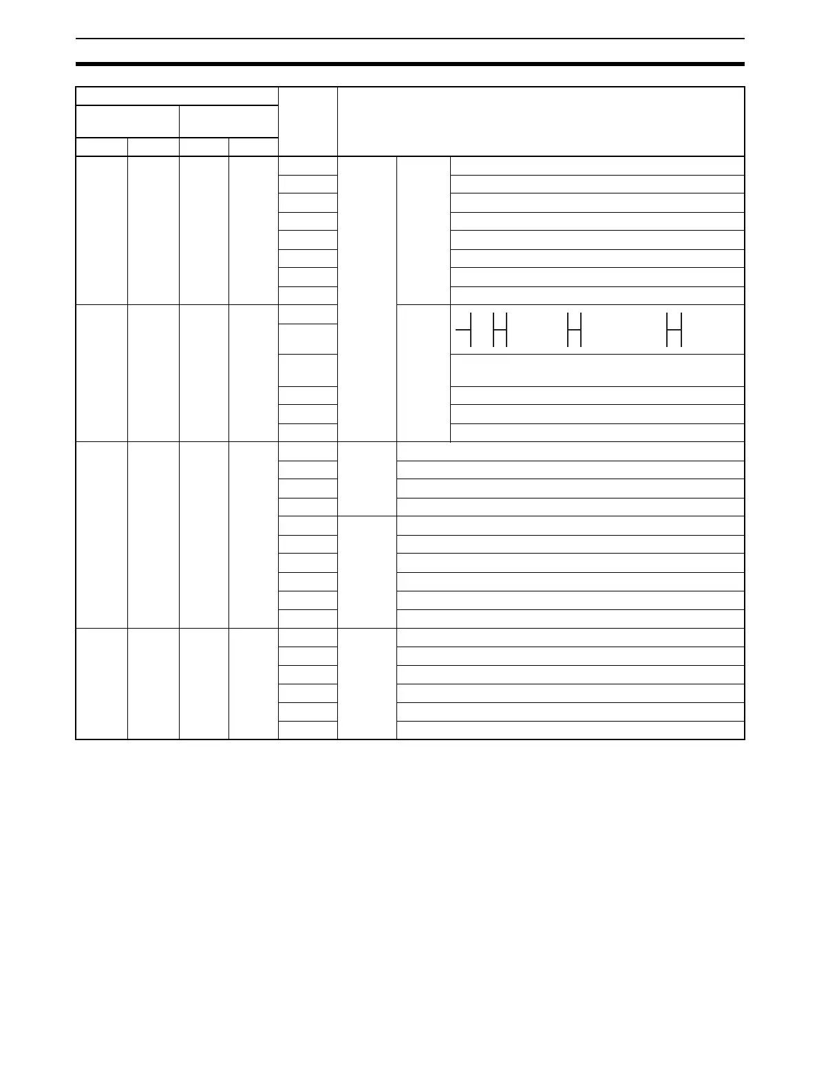
CIO
1905
CIO
1915
n + 5 n + 15 12 to 15 Port
setting
status
Setup
settings
Serial communications mode
08 to 11 Baud rate (See note.)
05 to 07 Reserved
04 Start bits: Always 0
03 Data length: 7 or 8 bits (See note.)
02 Stop bits: 1 or 2 bits (See note.)
01 Parity: Yes/No (Note)
00 Parity: Even/Odd (Note)
CIO
1906
CIO
1916
n + 6 n + 16 15 Hard-
ware
settings
14
13 0: Terminating resistance OFF
1: Terminating resistance ON
02 to 12 Reserved
01 1: Setup error; 0: Setup normal
00 1: Port operating; 0: Port stopped
CIO
1907
CIO
1917
n + 7 n + 17 11 to 15 Commu-
nica-
tions
status
Reserved
10 Undetermined
09 Reserved
08 Always 0
07 Trans-
mission
control
signal
status
ER signal
06 DTR signal
05 Reserved
04 CTS signal
03 RTS signal
00 to 02 Reserved
CIO
1908
CIO
1918
n + 8 n + 18 15 Trans-
mission
error sta-
tus
1: Transmission error; 0: No transmission error
05 to 14 Not used.
04 1: Overrun error; 0: Normal
03 1: Framing error; 0: Normal
02 1: Parity error; 0: Normal
00, 01 Reserved
Words Bit Contents
Boards
(CS Series only)
Units
(CS/CJ Series)
Port 1 Port 2 Port 1 Port 2
0 No 0 RS-232C 1 RS-422A/485 1 Reser ved
0 1 0 1

 Loading...


