257
Auxiliary Area and CIO Area Allocations Section 7-3
Note The port settings in the Setup Area allocated in the DM Area are stored. If the
Board/Unit is operating on default settings due to a System Setup error the
default settings will be stored.
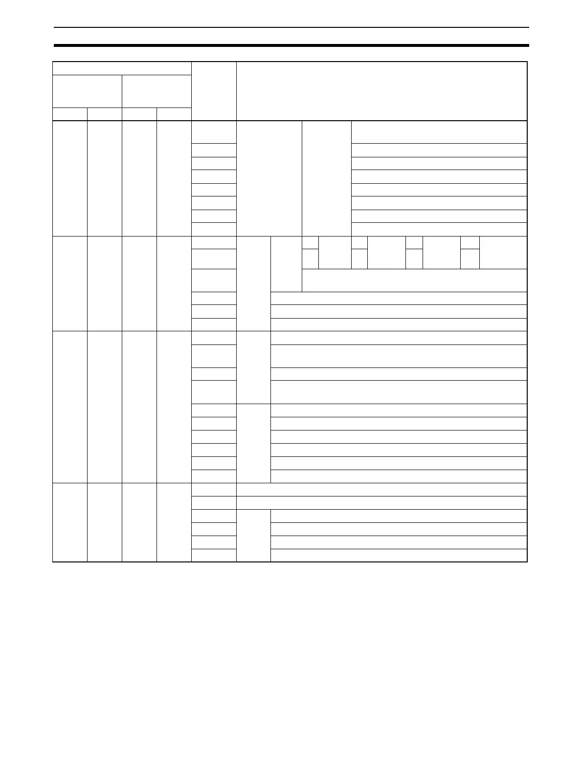
1905 1915 n+5 n+15 12 to 15 Port setting
status
System
settings
Serial communications mode: Always 3 hex
(See note.)
08 to 11 Baud rate (See note.)
05 to 07 Reserved
04 Start bits: Always 0
03 Data length (See note.)
02 Stop bits (See note.)
01 Parity: Yes/No (See note.)
00 Parity: Even/Odd (See note.)
1906 1916 n+6 n+16 15 Port
setting
status
Hard-
ware
set-
tings
0No 0RS-
232C
1RS-
422A/
485
1 Reserved
14 0 1 0 1
13 0: Terminating resistance OFF
1: Terminating resistance ON
02 to 12 Reserved
01 1: System Setup error; 0: System Setup normal
00 1: Port operating
1907 1917 n+7 n+17 11 to 15
Com-
munica-
tions
status
Reserved
10 1: Remote Unit busy receiving (Flow control)
0: Remote Unit ready to receive
09 Reserved
08 1: Local Unit busy receiving (Flow control)
0: Local Unit ready to receive
07 Trans-
mis-
sion
con-
trol
signal
status
DTR (ER) signal
06 DSR (DR) signal
05 Reserved
04 CTS (CS) signal
03 RTS RS) signal
00 to 02 Reserved
1908 1918 n+8 n+18 15 1: Transfer error; 0: Normal
05 to 14 Not used
04 Trans-
mis-
sion
error
status
1: Overrun error; 0: Normal
03 1: Framing error; 0: Normal
02 1: Parity error; 0: Normal
00, 01 Reserved
Words Bit Contents
Board
(CS Series
only)
Unit
(CS/CJ Series)
Port 1Port 2Port 1Port 2

 Loading...


