EasyManua.ls Logo

Omron SYSMAC NX-CIF105 User Manual

Omron SYSMAC NX-CIF105
232 pages
To Next Page IconTo Next Page
To Previous Page IconTo Previous Page
Page #189 background imageLoading...
Page #189 background image
A - 9
Appendices
NX-series Communications Interface Units User’s Manual (W540)
A-3 List of NX Objects
A
A-3-2 NX Objects for the NX-CIF101 and NX-CIF105
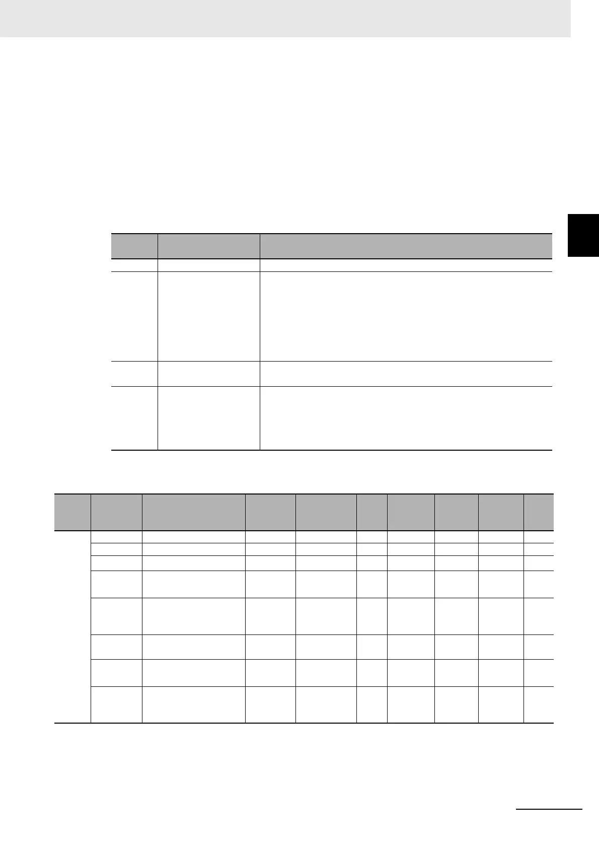
The following table shows the Input Sub Info. If the Input Data Type indicates a control command
response, the result of the control command is stored in the Input Sub Info.
*2. The value will be 2 hex only when the Number of Characters to Determine the End is set to a value other
than 0. If the Number of Characters to Determine the End is set to 0 and there is receive data, the value
will be 1 hex.
*3. If the Number of Characters to Determine the End is not set to 0, the value will be 1 hex when the final
receive data is received. The value will then change to 2 hex when the end is detected.
*4. Both data reception and a command response may occur at the same time.
*5. You cannot read this data as BOOL data. To read the command
code of a control command, access the
data as WORD data.
Value
(hex)
Execution result of
control command
Description
0000 Normal end Normal end
0001 Execution is not possi-
ble because an opera-
tion is in progress.
The RS Signal ON or RS Signal OFF control command was exe-
cuted when the flow control method was set
to RS/
CS flow control.
One of the following control commands was executed for the
NX-CIF105:
RS Signal ON, RS Signal OFF, ER Signal ON, or ER
Signal OFF
The Clear Serial Line Monitor Buffer control command was executed
when
serial line monitoring was in progress.
0002 Undefined command An undefined control command was specified and therefore it cannot
be executed.
0003 Setting out-of-range
error
The Change Number of Characters to Determine the End or Change
Communications Setup control command was executed and the
value of the Output Sub Info was out of range.
The Flow Control Method in the Output Sub Info for the NX-CIF105
was
set to RS/CS flow control.
Index
(hex)
Subindex
(hex)
Object name Default Data range Unit
Data
type
Access
I/O allo-
cation
Data
attri-
bute
7000 --- Ch1 Output Data --- --- --- --- --- --- ---
00 Ch1 Number of Entries 6 1 to 15 --- USINT RO No ---
01
Ch1 Output SID
*1
*1. The Input SID is incremented each I/O refresh from 01 hex to FF hex. It returns to 01 hex after FF hex. If the Output SID
is not changed from the previous transmission, it means there is no change to the output data or that there is no output
data.
00 hex --- --- USINT RW Yes ---
02 Ch1 Input SID
Response
*2
00 hex --- --- USINT RW Yes ---
03 Ch1 Output Data Type
(See below for details.)
0000 hex --- --- WORD
and
BOOL
RW Yes ---
04 Ch1
Output Sub Info
(See below for details.)
0000 hex --- --- WORD RW Yes ---
05 Ch1 Output Data
Len
gth [bytes]
*3
0 --- --- UINT RW Yes ---
06 to 19 Ch1 Output Data 01 to
20
*4
00 hex
420
--- --- ARRAY
[0..3] OF
BYTE
RW Yes ---

Table of Contents

Question and Answer IconNeed help?

Do you have a question about the Omron SYSMAC NX-CIF105 and is the answer not in the manual?

Omron SYSMAC NX-CIF105 Specifications

General IconGeneral
Number of Ports1
Port TypeRJ45
Operating Temperature0 to 55 °C
TypeCommunication Interface Unit
Compatible SeriesNX-series
Isolation Voltage500 VAC

Summary

Features and System Configuration

Features of Communications Interface Units

Details the features of the Communications Interface Units as Sysmac and NX devices.

System Configuration

Describes system configurations for connecting CIF Units to CPU Units or Coupler Units.

Unit Models, Functions, and Support Software

Outlines available CIF Unit models, their functions, and necessary support software.

Serial Communications Instructions for the CIF Units

Explains serial communication instructions for implementing no-protocol transfers.

Specifications and Application Procedures

Specifications

Provides general specifications and individual unit specifications for CIF Units.

Application Procedures

Details the procedures for setting up, wiring, and operating CIF Units.

Part Names and Functions

Part Names

Identifies and describes the physical parts of the CIF Units.

Indicators

Explains the indicators on the CIF Units and their operational meanings.

Installation and Wiring

Installing NX Units

Provides instructions for installing NX Units, including CIF Units.

Connecting the Power Supply and Ground Wires

Details how to connect power supply and ground wires to the CIF Units.

Wiring the Terminals

Explains how to wire the terminals on the CIF Units, including connector types.

Special Information

Precautions for Safe Use

Precautions on what to do and not to do to ensure safe usage.

Precautions for Correct Use

Precautions on what to do and not to do to ensure proper operation.

Safety Precautions

During Power Supply

Safety precautions related to the power supply.

Fail-safe Measures

Requirements for external fail-safe measures in the system.

Voltage and Current Inputs

Precautions regarding input voltage and current ranges.

Precautions for Safe Use

Installation

Safety precautions during the installation process.

Wiring

Safety guidelines for wiring communications cables.

Precautions for Correct Use

Storage, Mounting, and Wiring

Precautions for storing, mounting, and wiring Units correctly.

Regulations and Standards

Sections in this Manual

Features and System Configuration

Describes unit features and system configurations.

Specifications and Application Procedures

Provides specifications and application procedures.

Part Names and Functions

Details part names and functions of CIF Units.

Installation and Wiring

Covers installation and wiring procedures for CIF Units.

Troubleshooting

Provides error information and corrections.

I/O Data Specifications

Unit Settings

Serial Communications

Serial Line Monitor

Troubleshooting

How to Check for Errors

Methods for checking and identifying errors.

Checking for Errors with the Indicators

Using unit indicators to check for errors.

Checking for Errors and Troubleshooting on the Support Software

Troubleshooting errors using support software.

Resetting Errors

Procedures for resetting detected errors.

Troubleshooting Flowchart

A flowchart for the troubleshooting process.

Maintenance and Inspections

Related product manuals