RAD-...-IFS
102 / 198
PHOENIX CONTACT 105542_en_05
7.3.5 Setting the I/O MAP address
Use the thumbwheel to set the I/O MAP address. The extension module in the Radioline
wireless system is addressed using the I/O MAP address. Addresses 01 ... 99 (maximum)
can be assigned for the I/O extension modules in the entire wireless network.
7.3.6 Process data in PLC / Modbus/RTU mode
The process image of the I/O extension module consists of six data words. For additional
information, please refer to Section “RAD-AO4-IFS process data” on page 71.
7.4 RAD-DI4-IFS - digital extension module with four
inputs
The RAD-DI4-IFS digital I/O extension module can process up to four input signals. The dig-
ital inputs process the following voltages:
– 0 V ... 50 V AC/DC at the low voltage input
– 0 V ... 250 V AC/DC at the high voltage input
All inputs are electrically isolated from one another, from the supply voltage, and from the
electronics.
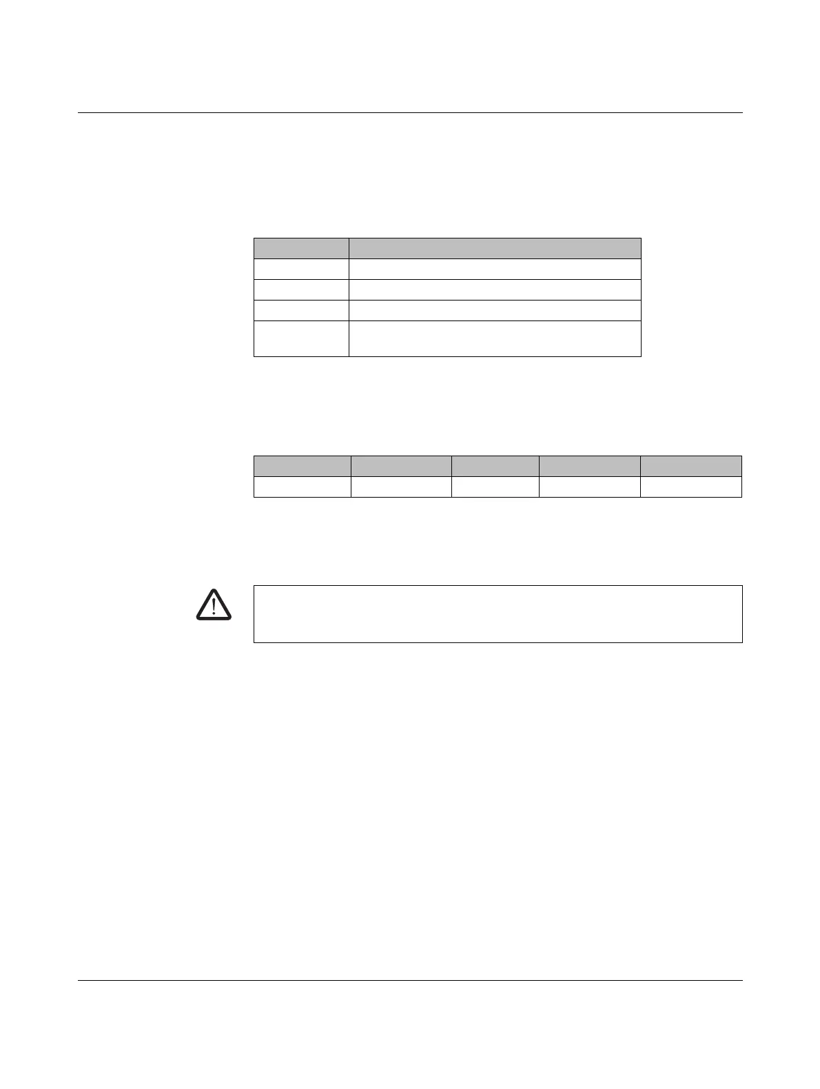
Table 7-6 Setting the I/O MAP address for the RAD-AO4-IFS
Thumbwheel Description
01 ... 99 I/O MAP address
00 Delivery state
**, 1* ... 9* Setting not permitted
*1 ... *9 Interface system slave address, for use with other
interface system (IFS) master devices
I/O module Module type ID Register Address range Function code
RAD-AO4-IFS 30
hex
06
hex
40xx0 ... 40xx5 fc 03, 16
WARNING: Risk of electric shock
Use the same phase for digital inputs and outputs. The isolating voltage between the
individual channels must not exceed 300 V.
 Loading...
