RAD-....-IFS
62 / 198
PHOENIX CONTACT 105542_en_05
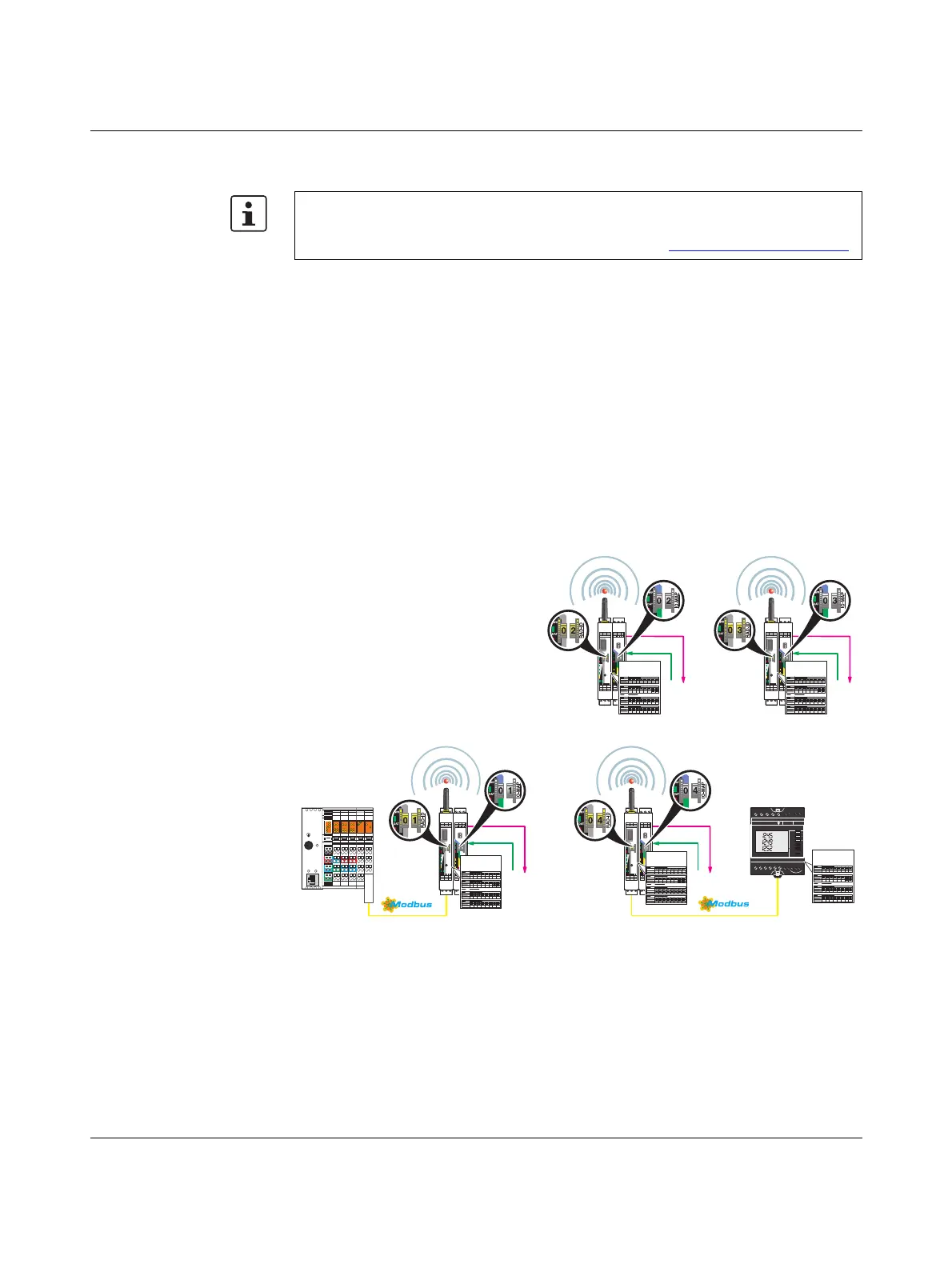
6.2 PLC / Modbus/RTU dual mode
Dual mode combines PLC / Modbus/RTU mode and serial data mode. You can connect
Radioline extension modules to the controller directly via the integrated RS-232 and RS-485
interface by means of wireless communication. You can also connect additional
Modbus/RTU slaves in parallel.
In dual mode, each station in the wireless network acts as an independent Modbus slave.
The yellow RAD ID corresponds to the Modbus address. The Modbus address of the mas-
ter wireless module (RAD ID = 01) can be changed in order to integrate the wireless system
into an existing Modbus network with Modbus address 01.
You can connect I/O extension modules to each station in the network. All I/O data from the
extension modules is stored locally in the Modbus memory map of the respective station.
Concurrently, you can connect additional Modbus slaves to each wireless station via
RS-232 or RS-485, and control them via the respective Modbus address. All diagnostic data
of the wireless network can be read from the wireless master (RAD ID = 01) of the wireless
network via Modbus/RTU.
Figure 6-4 Configuration example: PLC / Modbus/RTU dual mode
PLC / Modbus/RTU dual mode is available for firmware version 1.80 or later. You can
update the firmware free of charge using the PSI-CONF software version 2.50 or later.
The firmware and software can be found on the Internet at phoenixcontact.net/products
.
RAD-ID
SPORT
PWR
DAT
ERR
RXTX
0
1
Reset
D(A)
D(B)
RX
CO
1
TX
CO
2
GND
NC
1
+24V
RSSI
+
0V
ANT
RSSI
-
IO-MAP
PWR
DAT
ERR
DO2
DO1
DI2
DI1
OFF ON
DIP-1
1
2
3
4
DI1L
DI2L
DI1H
DI2H
DI1
DI2
UL1 +I1 -I1
U1 I1
1
COM1
COM2
NO1
NO2
NC1
NC2
0 1
RESET
MRESET
STOP
RUN/PROG
X1
LNK ACT
PRG
1.1
D
TR
2.1
1.2
1.3
1.4
2.2
2.3
2.4
1.1
TxD
TxD
2.1
1.2
1.3
1.4
2.2
2.3
2.4
1.1 2.1
1.2
1.3
1.4
2.2
2.3
2.4
1.1 2.1
1.2
1.3
1.4
2.2
2.3
2.4
1.1 2.1
1.2
1.3
1.4
2.2
2.3
2.4
1.1 2.1
1.2
1.3
1.4
2.2
2.3
2.4
RAD-ID
SPORT
PWR
DAT
ERR
RXTX
0
4
Reset
D(A)
D(B)
RX
CO
1
TX
CO
2
GND
NC
1
+24V
RSSI
+
0V
ANT
RSSI
-
IO-MAP
PWR
DAT
ERR
DO2
DO1
DI2
DI1
OFF ON
DIP-1
1
2
3
4
DI1L
DI2L
DI1H
DI2H
DI1
DI2
UL1 +I1 -I1
U1 I1
1
COM1
COM2
NO1
NO2
NC1
NC2
0 4
kW
kvarh
kVA
COM
L1
L2
L3
I
U F
PPF
E
12 14 162188102022
1 35 7911 4 6 13 15 17
V1 V2 V3 VN
Input Aux Supply
S1 S2 S1 S2 S1 S2
I1 I2 I3Output RS485
°C
TEST
OK
PROG
+- +-
C=0,1Wh/imp
RAD-ID
SPORT
PWR
DAT
ERR
RXTX
0
2
Reset
D(A)
D(B)
RX
CO
1
TX
CO
2
GND
NC
1
+24V
RSSI
+
0V
ANT
RSSI
-
IO-MAP
PWR
DAT
ERR
DO2
DO1
DI2
DI1
OFF ON
DIP-1
1
2
3
4
DI1L
DI2L
DI1H
DI2H
DI1
DI2
UL1 +I1 -I1
U1 I1
1
COM1
COM2
NO1
NO2
NC1
NC2
0 2
RAD-ID
SPORT
PWR
DAT
ERR
RXTX
0
3
Reset
D(A)
D(B)
RX
CO
1
TX
CO
2
GND
NC
1
+24V
RSSI
+
0V
ANT
RSSI
-
IO-MAP
PWR
DAT
ERR
DO2
DO1
DI2
DI1
OFF ON
DIP-1
1
2
3
4
DI1L
DI2L
DI1H
DI2H
DI1
DI2
UL1 +I1 -I1
U1 I1
1
COM1
COM2
NO1
NO2
NC1
NC2
0 3
Analog IN
Digital OUT
RAD-Repeater/Slave
Modbus-Slave 2
RAD-ID
I/O-MAP
Modbus-Register
Analog IN
Digital OUT
RAD-Repeater/Slave
Modbus-Slave 3
RAD-ID
I/O-MAP
Modbus-Register
Modbus/RTU-
Master
Analog IN
Digital OUT
RAD-Master
Modbus-Slave 1
RAD-ID
I/O-MAP
Modbus-Register
Analog IN
Digital OUT
RAD-Repeater/Slave
Modbus-Slave 4 Modbus-Slave 5
RAD-ID
I/O-MAP
Modbus-Register
Modbus-Register
 Loading...
