Description of I/O extension modules
105542_en_05 PHOENIX CONTACT 103 / 198
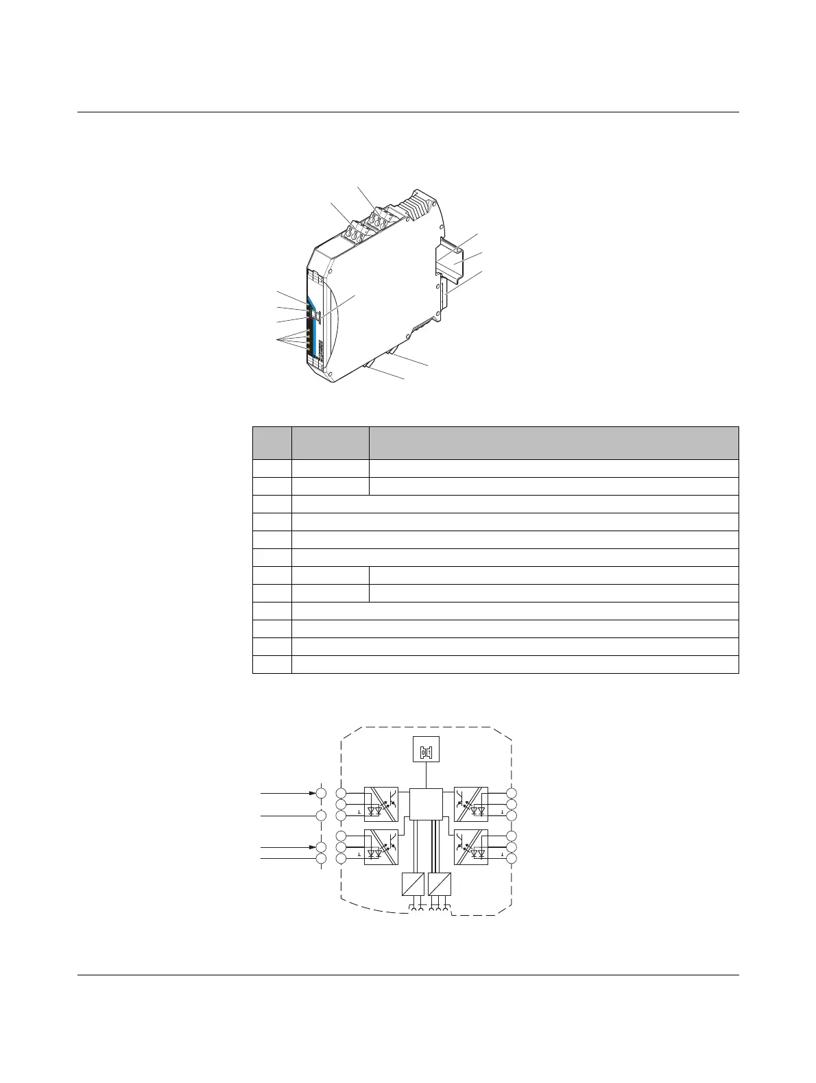
7.4.1 Structure
Figure 7-18 RAD-DI4-IFS structure
7.4.2 Basic circuit diagram
Figure 7-19 Basic circuit diagram for the RAD-DI4-IFS
Item Ter mi na l
block
Designation
1 2.1/2.2/2.3 Digital input as wide-range input
2 1.1/1.2/1.3 Digital input as wide-range input
3 White thumbwheel for setting the I/O MAP address
4 Connection option for DIN rail connector
5DIN rail
6 Metal foot catch for DIN rail fixing
7 5.1/5.2/5.3 Digital input as wide-range input
8 6.1/6.2/6.3 Digital input as wide-range input
9 Status LEDs for digital inputs DI1 ... DI4
10 ERR status LED, red (communication error)
11 DAT status LED, green (bus communication)
12 PWR status LED, green (supply voltage)
DI
4L
DI
3L
IO-MAP
RAD-DI4-IFS
P
WR
DA
T
E
RR
D
I1
D
I2
D
I3
D
I4
8
8
D
I
4
DI
3
DI
4H
DI
3H
D
I
2L
D
I
1L
DI
2
D
I
1
D
I
2H
DI
1H
DI
2L
D
I
1L
DI
2
D
I
1
DI
2
H
D
I
1H
1
2
3
4
6
7
12
11
10
8
5
9
10...50V AC/DC
2.1
2.3
GND
GND
1.2
1.3
50...250V AC/DC
IO-MAP
µC
DC
DC
IFS
IFS
DI
2L
DI
2H
DI
2
DI
1L
DI
1H
DI
1
DI
3L
DI
3H
DI
3
DI
4L
DI
4H
DI
4
2.1
2.2
2.3
1.1
1.2
1.3
6.1
6.2
6.3
5.1
5.2
5.3
 Loading...
