RAD-...-IFS
118 / 198
PHOENIX CONTACT 105542_en_05
7.7.4 Diagnostic LEDs
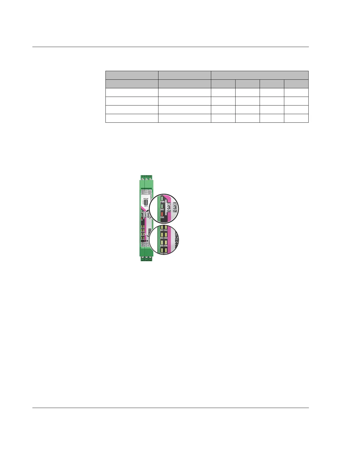
The RAD-DO8-IFS I/O extension module uses a total of eleven LEDs to indicate the oper-
ating states.
Figure 7-32 Diagnostics LEDs of the RAD-DO8-IFS
PWR LED
The green PWR LED indicates the status of the supply voltage.
DAT LED
The green DAT LED indicates the status of bus communication.
Table 7-12 DIP switches of the RAD-DO8-IFS
DIP switch
Setting Output signal 1 2 3 4
Digital OUT 1 ... 4 RESET OFF n. c. n. c.
Digital OUT 1 ... 4 HOLD ON n. c. n. c.
Digital OUT 5 ... 8 RESET OFF n. c. n. c.
Digital OUT 5 ... 8 HOLD ON n. c. n. c.
n. c. = not connected, DIP switches 3 and 4 have no function
Off No supply voltage
On Supply voltage OK
Off No communication
Flashing Configuration and addressing mode
On Cyclic data communication
 Loading...

