Description of I/O extension modules
105542_en_05 PHOENIX CONTACT 121 / 198
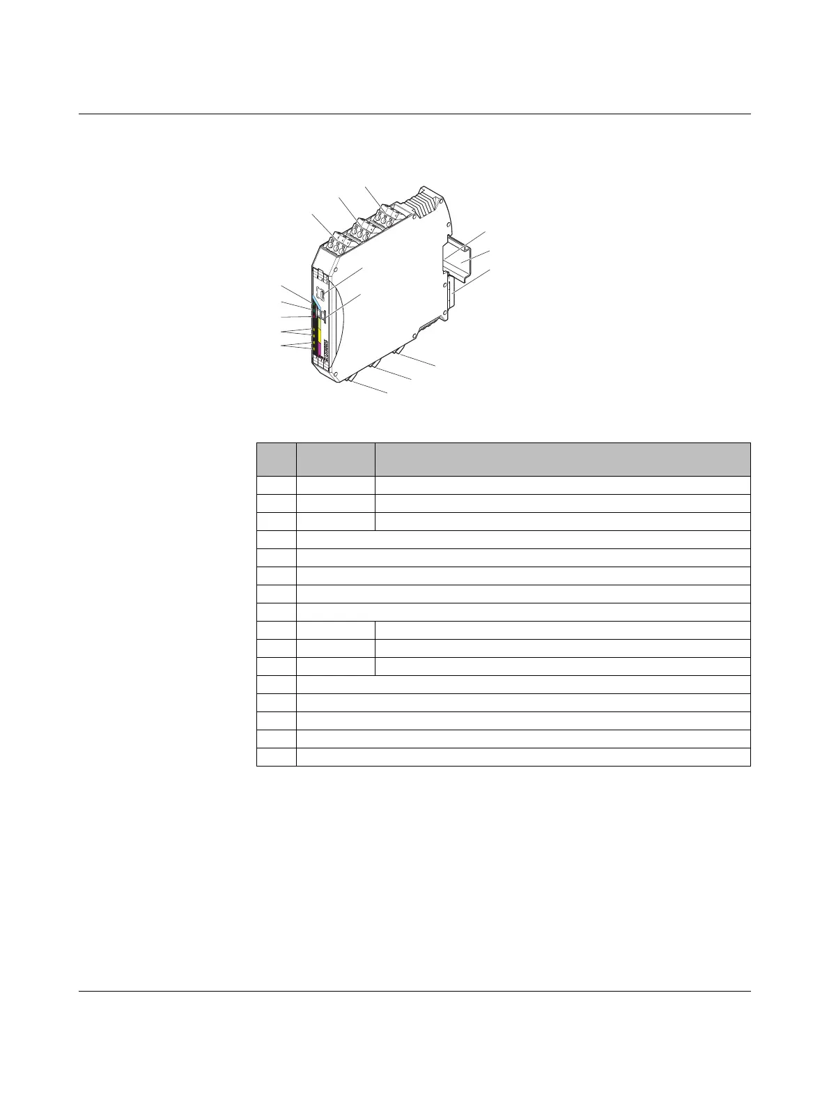
7.8.1 Structure
Figure 7-33 RAD-DAIO6-IFS structure
Item Ter mi na l
block
Designation
1 3.1/3.2/3.3 Analog input for 2, 3, 4-wire measuring transducers
2 2.1/2.2/2.3 Digital input as wide-range input
3 1.1/1.2/1.3 Digital input as wide-range input
4 DIP switches for configuring the inputs and outputs
5 White thumbwheel for setting the I/O MAP address
6 Connection option for DIN rail connector
7DIN rail
8 Metal foot catch for DIN rail fixing
9 4.1/4.2/4.3 Analog output, either current or voltage
10 5.1/5.2/5.3 Relay output with floating changeover contact
11 6.1/6.2/6.3 Relay output with floating changeover contact
12 Status LEDs of digital outputs DO1 ... DO2
13 Status LEDs of digital inputs DI1 ... DI2
14 ERR status LED, red (communication error)
15 DAT status LED, green (bus communication)
16 PWR status LED, green (supply voltage)
P
w
r
1
+
I
1
DI
2
L
D
I
1
DI
2
D
I
1
H
D
I
2
H
D
I
1L
-
I
1
1
2
4
5
6
8
10
16
15
14
9
7
3
11
13
12
PW
R
DA
T
ER
R
D
I1
DI2
D
O
1
D
O2
8
8
1
2
3
4
OF
F
O
N
D
IP
-1
U
1
1
I
1
C
O
M
1
IO-MAP
RAD-DAIO6-IFS
CO
M
2
P
w
r
1
+I
1
NC
2
NC
1
N
O
2
N
O
1
D
I
2
L
D
I
1
D
I
2
DI
1
H
D
I
2
H
D
I
1
L
-I
1
 Loading...
