SHOULD ANY INTERVENTIONS TO THE ELECTRIC SYSTEM BE REQUIRED, MAKE SURE THAT
THE LEADS TO THE ELECTRONIC IGNITION DEVICE ARE PROPERLY CONNECTED ACCORD-
ING TO POLARITY AND TO THE LEAD COLOURS.
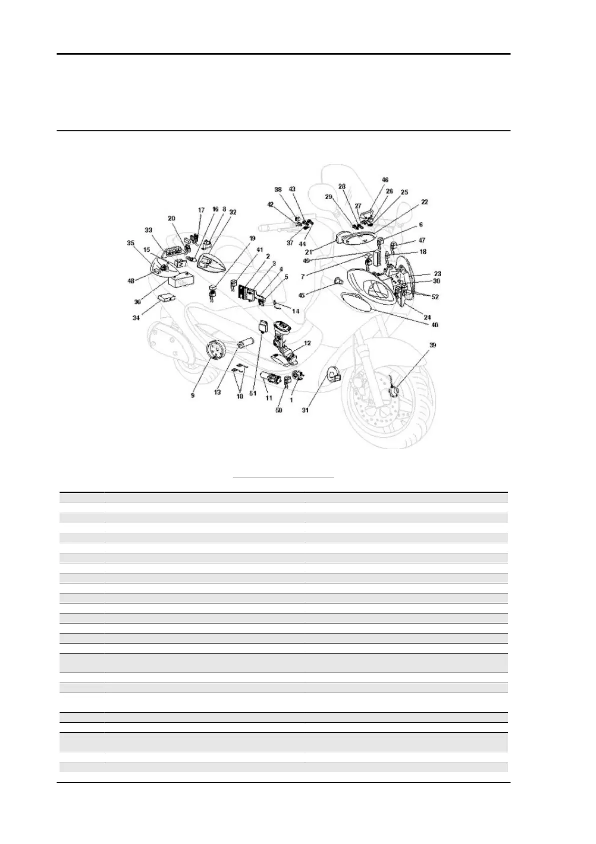
Components arrangement
COMPONENTS LOCATION
Specification
Desc./Quantity
1 Side stand switch
2 Voltage regulator
3 Side stand control unit
4 Electronic control unit remote control switch
5 Engine stop remote control switch
6 Service remote control switch
7 Fuse holder box (n.3 7.5A, n.1 15A)
8 No. 2 start-up remote control switches
9 Magneto flywheel 373W
10 No. 2 buttons for side stand
11 Side stand pump motor
12 Pump unit with level indicator
13 Starter motor
14 Helmet compartment lighting button
15 Helmet compartment glass bowl
16 Socket 12V
17 No. 2 rear fuse holder boxes for control unit (n.1 3A, n.1
5A, n.1 10A, n.1 3A)
18 (Diode holder box (n. 2 6A and 2A diodes)
19 Fuse holder box (n.2 7.5A, n.1 15A and 5A)
20 Fuse holder box with base for stand pump remote control
switch (n.1 70A)
21 Digital instrument unit (11 indicators and led)
22 Analogue instrument unit (5 bulbs)
23 Headlight with n. 2 position bulbs and n.2 high/low beam
bulbs 55W
24 Front LH direction indicator with 10W bulb
25 Rear brake stop button
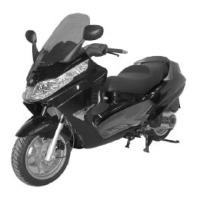
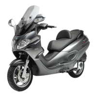
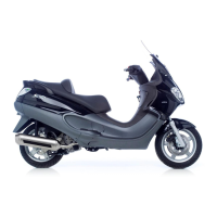
Electrical system X9 Evolution 500
ELE SYS - 56

 Loading...