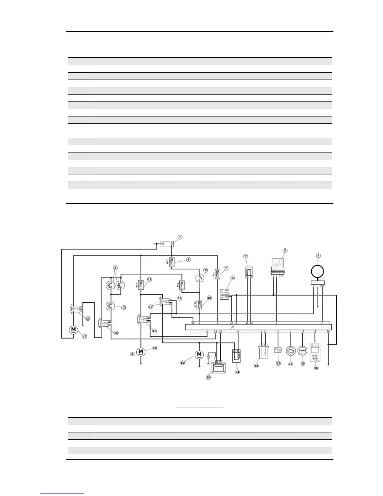
Specification Desc./Quantity
9 Water temperature sensor
10 Can «H» Line
11 + Lambda probe
12 Engine stop switch
13 R.P.M. sensor (+)
14 Fuel injector
15 R.P.M. sensor (-)
16 Diagnostics socket output
17 Immobilizer LED
18 Ground lead Connected to the engine stop switch and the
water temperature sensor.
19 -
20 Injection load remote control
21 -
22 HV coil
23 -
24 Start up enabling
25 -
26 Ground lead
EMS circuit diagram
SYSTEM SCHEMATIC
Specification Desc./Quantity
1 Battery 12V - 12 Ah
2 Engine rpm sensor
3 Water temperature sensor
4 Immobilizer aerial
5 Stop button
MP3 400 i.e. Injection
INJEC - 7
 Loading...