7A. Potentiometer ground lead, rpm sensor, rider
presence sensor (Yellow)
8. Ground (Black)
1B. Live supply (Yellow-Red)
2B. CAN "H" Line (Pink-White)
3B. Left wheel turning sensor (Green)
4B. Right wheel turning sensor (Red)
5B. Potentiometer signal (Green-Blue)
6B. Locking/unlocking switch (Green-Grey)
7B. Horn remote control for alarms (White)
8B. Geared motor (White-Red)
1C. Battery powered (Blue-Red)
2C. Diagnosis (Purple-White)
3C. Locking/unlocking switch (Yellow-Blue)
4C. Calliper sensor (Brown)
5C. Locking/unlocking switch (Purple-Black)
6C. Rider presence sensor (Purple)
7C. Scooter speed signal (Sky blue)
8C. Geared motor (Blue)
Remote seat opening
Zeroing
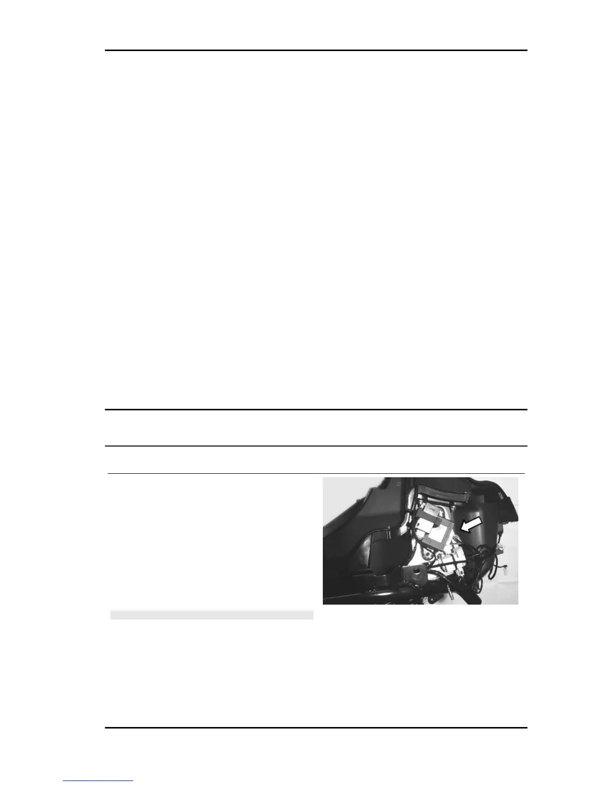
- Remove the left side fairing to access the saddle
opening receiver control unit indicated in the pho-
tograph
- Remove the metal terminal and connect it to a
good earth point, or to terminal 7 (black), for at
least 10 seconds.
- In this operation all the remote controls stored in
the control unit will be deleted.
WARNING
THE CONTROL UNIT CAN PROGRAMME UP
TO 8 REMOTE CONTROLS.
MP3 400 i.e. Electrical system
ELE SYS - 33