Removing the clutch
- To remove the clutch with the driven pulley it is
necessary to use the special tool;
- Arrange the tool with the mean pins screwed in
position "E" on the inside;
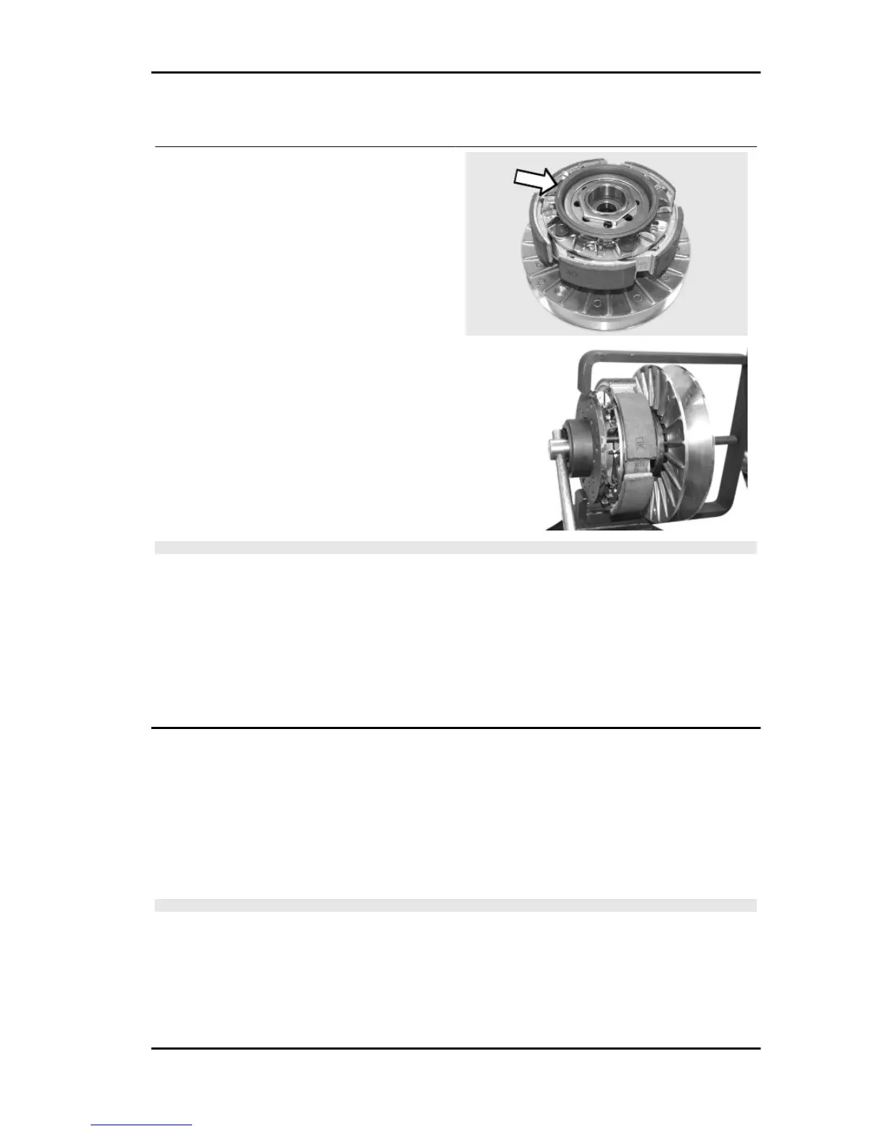
- Fit the adapter ring to the clutch assembly as
shown in the photograph.
- Install the driven pulley unit onto the tool inserting
the pins into the ventilation holes;
- Move the rear stop screw in abutment against the
fixed driven pulley as shown in the figure.
CAUTION
THE TOOL SHOULD BE FIRMLY SECURED IN A VICE USING THE SPECIAL TOOL. DO NOT
TIGHTEN THE REAR SCREW TOO MUCH AS THIS COULD CAUSE AN IRREVERSIBLE TOOL
DEFORMATION.
USING THE SPECIAL 55-MM WRENCH, REMOVE THE FASTENING RING NUT.
LOOSEN THE TOOL SCREW AND DISASSEMBLE THE DRIVEN PULLEY UNIT, CLUTCH, SPRING
WITH SHEATH.
Specific tooling
020444Y Tool for fitting/ removing the driven pulley clutch
Inspecting the clutch
- Check the thickness of the clutch mass friction material.
Characteristic
Minimum thickness permitted:
1 mm
- The masses must not show traces of lubricants. Otherwise, check the driven pulley unit seals.
N.B.
UPON RUNNING-IN, THE MASSES MUST EXHIBIT A CENTRAL CONTACT SURFACE AND MUST
NOT BE DIFFERENT FROM ONE ANOTHER. VARIOUS CONDITIONS CAN CAUSE THE CLUTCH
TO TEAR.
MP3 400 i.e. Engine
ENG - 7

 Loading...