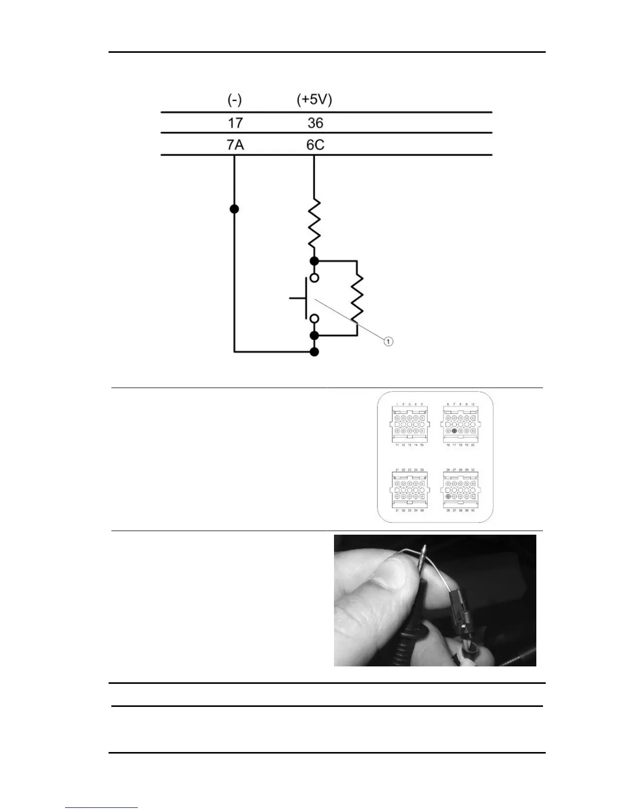
1: RIDER PRESENCE SENSOR
With interface wiring disconnected from the control
unit and connected to the system, check the fol-
lowing conditions:
pin 17 - 36: resistance 15 ÷ 18 kOhm when the
rider is not seated on the saddle.
pin 17 - 36: resistance of about 3 kOhm when the
rider is seated on the saddle
Check the continuity between the interface wiring
pin 17 and the yellow cable of the rider presence
connector.
Check the continuity between the interface wiring
pin 36 and violet cable of the rider presence con-
nector.
TILT LOCKING CALLIPER SENSOR
MP3 400 i.e. Suspensions
SUSP - 35
 Loading...