4.14
FUEL INJECTION
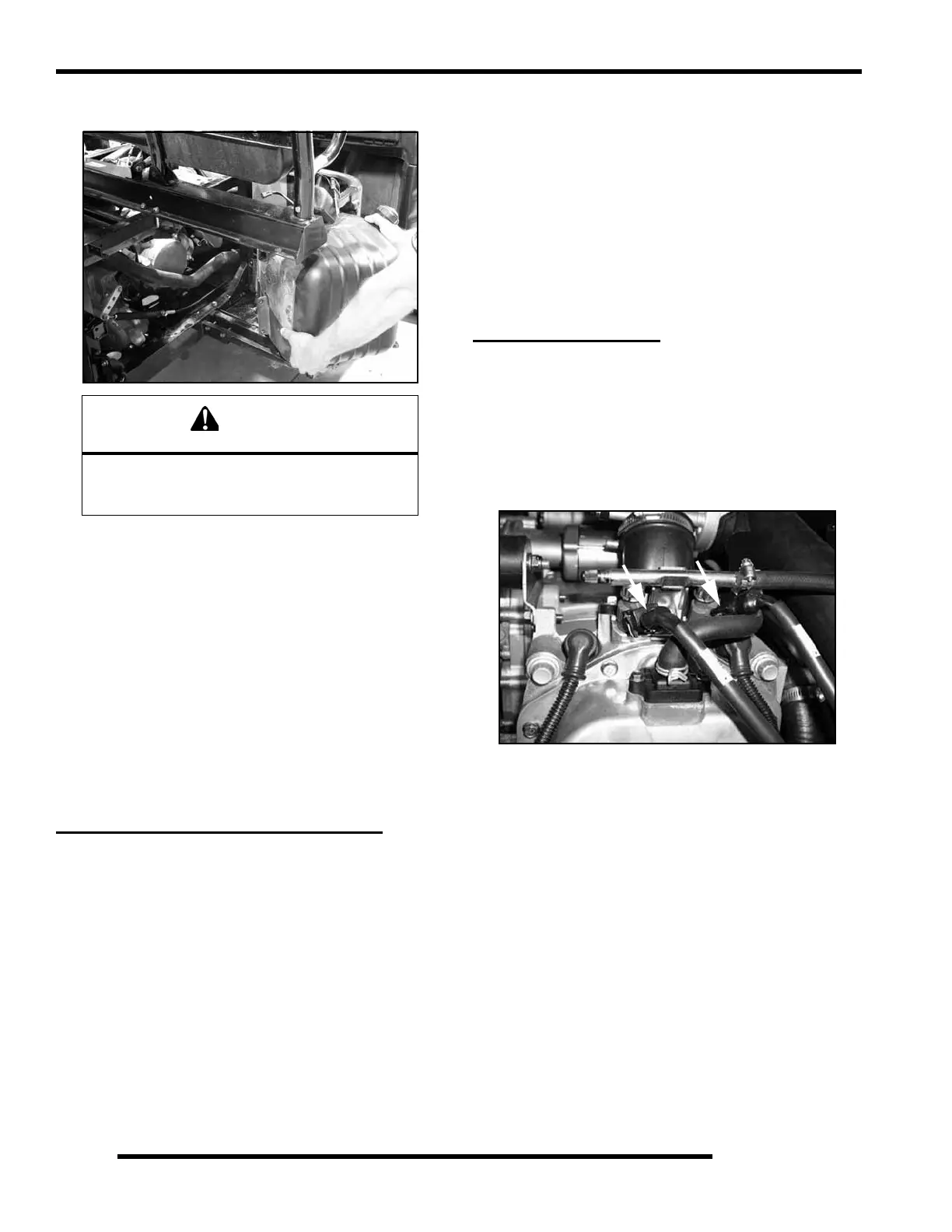
9. Reinstall the fuel cap and carefully pull the fuel tank out the
RH side of the frame.
Fuel Tank Installation
1. Reinstall the pump/tank assembly.
2. Reinstall the four fuel tank mounting bolts that were
removed.
3. Reconnect the electrical harness. Install the fuel line and
vent line and verify they are secure.
4. Reinstall the RH rear fender.
5. Reconnect the negative battery cable. Test the fuel pump
by turning on the key and listening for the pump to activate.
FUEL PRESSURE REGULATOR
Operation Overview
The fuel pressure regulator maintains the required operating
system pressure of 39 psi + 3psi. A rubber-fiber diaphragm
divides the regulator into two separate sections-, the fuel
chamber and the pressure regulating chamber. The pressure
regulating spring presses against the valve holder (part of the
diaphragm), pressing the valve against the valve seat. The
combination of atmospheric pressure and regulating spring
tension equals the desired operating pressure. Any time the fuel
pressure against the bottom of the diaphragm exceeds the
desired (top) pressure, the valve opens, relieving the excess
pressure, returning the excess fuel back to the tank.
Fuel Pressure Regulator Test
Refer to the “FUEL PUMP TEST” procedure.
See “Fuel Pump Test” on page 4.12.
Fuel Pressure Regulator Replacement
The regulator is a sealed, non-serviceable assembly. If it is
faulty, the pump assembly must be replaced. Refer to the Fuel
Pump / Tank Assembly Replacement procedure.
FUEL INJECTORS
Operation Overview
NOTE: All EFI units utilize quick connect fuel lines.
The fuel injectors mount into the intake manifold, and the fuel
rail attaches to them at the top end. Replaceable O-rings on both
ends of the injector prevent external fuel leaks and also insulate
it from heat and vibration.
When the key switch is on, the fuel rail is pressurized, and
voltage is present at the injector. At the proper instant, the ECU
completes the ground circuit, energizing the injector. The valve
needle in the injector is opened electromagnetically, and the
pressure in the fuel rail forces fuel down through the inside. The
“director plate” at the tip of the injector (see inset) contains a
series of calibrated openings which directs the fuel into the
intake port in a cone-shaped spray pattern.
The injector is opened and closed once for each crankshaft
revolution, however only one-half the total amount of fuel
needed for one firing is injected during each opening. The
amount of fuel injected is controlled by the ECU and determined
by the length of time the valve needle is held open, also referred
to as the “injection duration” or “pulse width”. It may vary in
length from 1.5-8 milliseconds depending on the speed and load
requirements of the engine.
WARNING
Wear safety goggles while performing this
procedure, failure to do so could result
in serious injuries.
 Loading...