2. Connectors
This is the QMX left panel.
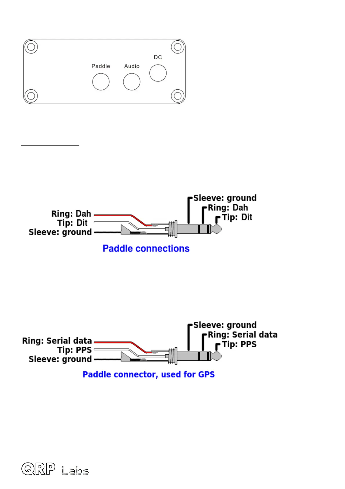
Paddle connector
The paddle connector is a 3.5mm stereo jack socket and actually has THREE purposes:
1) Paddle for CW operation
Don’t worry if your paddle has a reversed pinout, or if you connect the dit and dah to a 3.5mm jack
plug incorrectly: there is a configuration item in the configuration menu (CW Keyer menu) allowing
you to swap the dit and dah in the firmware.
2) GPS interface
Here the 1pps signal from the GPS must be connected to the 3.5mm jack “tip” connection, and the
serial data (9600 baud) to the “ring” connection. In QMX these signals are 3.3V logic level;
however they are connected to 5V-tolerant I/O pins on the microcontroller so 5V logic level will
also work fine. If you are using a GPS module directly, and it has the common 2.8V output logic,
this will also work fine.
QMX operang manual; rmware 1_00_012 7