Chapter 2: Installing the Chassis
Testing Chassis Connections
QX and QXS Setup Guide 85
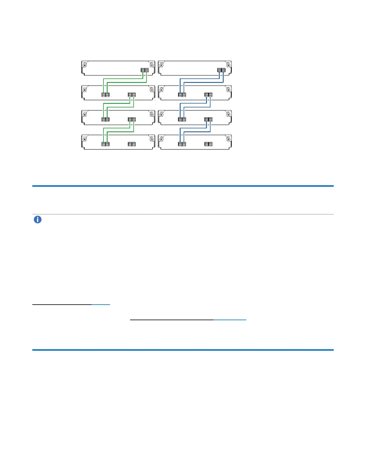
Figure83:Straight-through cabling between a dual-controller RAID chassis and 3 drive expansion chassis
RAID
Chassis 0
Expansion
Chassis 1
In
OutOut
0B
0A
1A
1B
Controller A
Controller B
In
In
OutOut
2A
2B
In
In
OutOut
3A
3B
In
Expansion
Chassis 2
Expansion
Chassis 3
Testing Chassis Connections
Note:For NEBS applications, verify that you are using compatible power supplies, RAID chassis, and
expansion chassis.
Power cycling procedures vary according to the type of power supply provided with the chassis. Some
chassis models are equipped with power supplies possessing power switches; whereas other chassis use
power supplies that have no power switch.
The 2U12 and 2U24 chassis use a common PSU model for AC and a common PSU model for DC. The
4U56 chassis use a different PSU model for AC and a different PSU model for DC. The 2U48 chassis use
an AC PSU model that is equipped with a power switch; the 2U48 chassis does not presently support a DC
PSU.
Power On/Power Off below describes power cycling procedures relative to different types of power supplies
installed within chassis . Once the power-on sequence succeeds, the storage system is ready to be
connected to hosts as described in Connect the Chassis to Hosts on page 95.
Power On/Power Off
Powering On the Chassis/System
Before powering on the chassis for the first time:
 Loading...


