Chapter 6: LEDDescriptions
LEDs for 56-Drive RAID Chassis (4U56)
QX and QXS Setup Guide 181
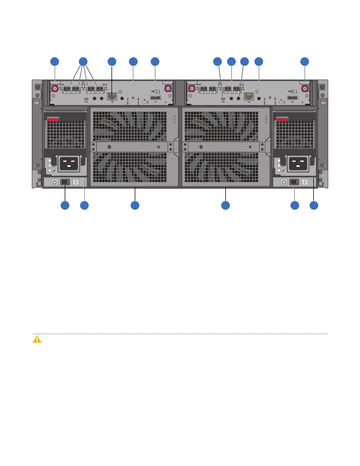
Figure128:QXS-5600 rear panel
LINK SERVICE–1
CACHE
DIRTY
CLEAN
LINK
ACTSERVICE–2 CLI
CLI
PORT 0 PORT 1
PORT 2 PORT 3
LINK SERVICE–1
CACHE
DIRTY
CLEAN
LINK
ACTSERVICE–2 CLI
CLI
PORT 0 PORT 1
PORT 2 PORT 3
1
2
6
7 8
9
10 11 12 13
3 4 5 5 3 4
1. ControllerI/OmoduleA
2. ControllerI/OmoduleB
3. ACpowersupplyswitch
4. ACpowersupply
5. Fancontrolmodule
6. CNCports:usedforhostconnectionorreplication
7. Networkport
8. Disabledbutton(usedbyengineering/testonly)
(Stickersshowncoveringtheopenings)
9. SASexpansionport
10. CLIport(USB-TypeB)
11. Serviceport2(usedbyservicepersonnelonly)
12. Reservedforfutureuse
13. Serviceport1(usedbyservicepersonnelonly)
The RAID Chassis accommodates two controller I/O modules of the same type within the I/O module (IOM)
slots (see callouts No.1 and No.2 above). The RAID Chassis accommodates two AC power supplies within
the two power supply slots (see two instances of callout No.4 above). Beneath each power supply is a
power supply switch (see two instances of callout No.3 above). The RAID Chassis accommodates two fan
control modules (see two instances of callout No.5 above).
Caution:The 56-drive RAID Chassis supports dual-controller configuration only. Single-controller
support is provided only when a controller fails over to its partner controller. A controller module must
be installed in each IOM slot to ensure sufficient airflow through the chassis during operation.
Controller I/O Module LEDs
The following figure provides a representative example of the controller I/O module. It lists the location and
description of the controller I/O module LEDs.
 Loading...


