Chapter 6: LEDDescriptions
LEDs for 56-Drive Expansion Chassis
QX and QXS Setup Guide 185
Power Supply LEDs
Power redundancy is achieved through two independent load-sharing power supplies. In the event of a
power supply failure, or the failure of the power source, the storage system can operate continuously on a
single power supply. Greater redundancy can be achieved by connecting the power supplies to separate
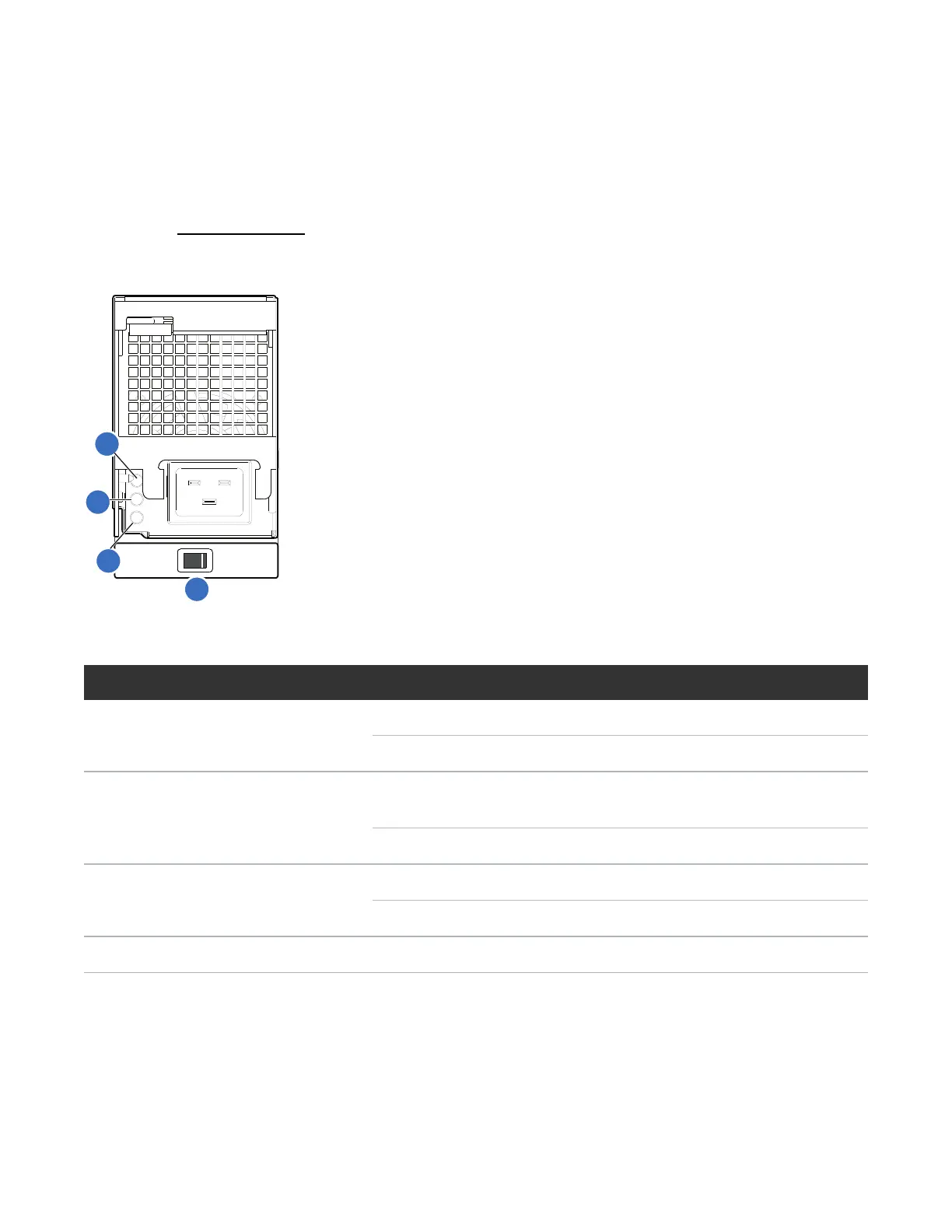
circuits. See Figure 131 below for power supply LEDs and description.
Figure131:LEDs: Power supply units — rear panel
LEDNo./Description Color State Definition
1 — AC Input Source Green On Power is on and input voltage is normal.
Off No AC input to power supply.
2 — Voltage/Fan
Fault/Service Required
Amber On
Blinking
Output voltage is out of range, or a fan is operating below
the minimum required RPM.
Off Fault not detected.
3 — DC Power Green On Main output power on.
Off Power is off; main output is off; or a fault is detected.
4 — Power supply switch NA NA NA
Table60:Power supply LEDs
 Loading...


