Smart Module Series
SG368Z_Series_Hardware_Design 35 / 113
⚫
3.1.3. Requirements for Voltage Stability
The recommended power supply voltage of the module is 3.4 V. The power supply performance, such as
load capacity, voltage ripple, etc. will directly influence the module’s performance and stability. Under
ultimate conditions, the module may have a transient peak current up to 3 A*. If the power supply
capability is not sufficient, there will be voltage drops, and if the voltage drops below 3.3 V, the module will
turn off automatically. Therefore, ensure the input voltage never drops below 3.3 V.
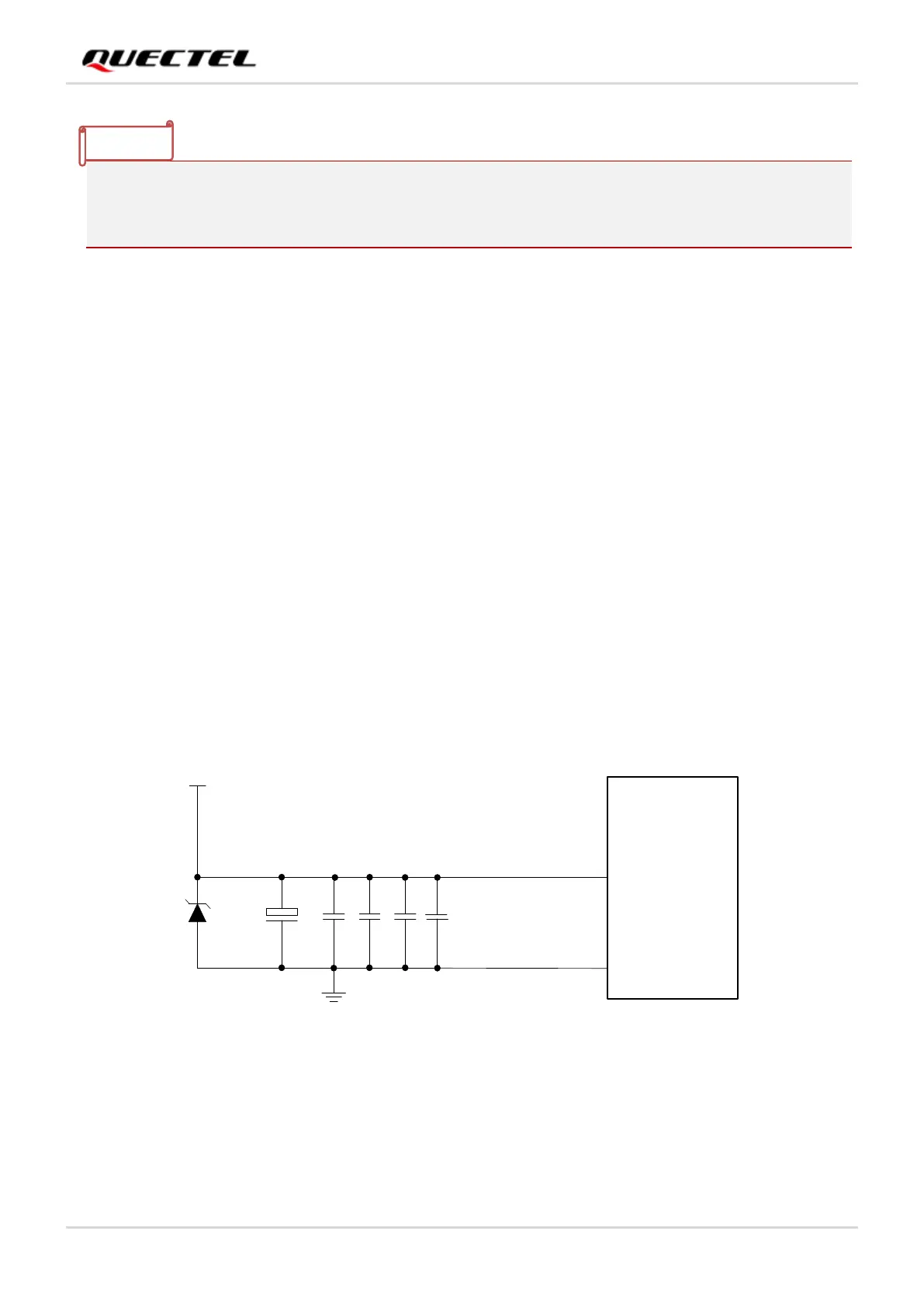
To prevent the voltage from dropping below 3.3 V, it is recommended to connect a 100 µF bypass
capacitor with low ESR as well as 4.7 μF, 100 nF, 33 pF and 10 pF filter capacitors in parallel near the
VBAT pins of the module. It is also recommended that the PCB traces of VBAT should be as short as
possible and wide enough to reduce the equivalent impedance of the VBAT traces and ensure that there
will be no large voltage drop under high current at the maximum transmission power. The width of VBAT
trace should be at least 3 mm*. As per design rules, the longer the VBAT trace is, the wider it should be.
Additionally, the ground plane of the power supply part should be as complete as possible.
To suppress the impact of power fluctuations and ensure the stability of the output power supply, it is
suggested to add a TVS component of at least 2000 W and place it as close to the VBAT pins as possible
to enhance surge protection. The following figure shows a reference circuit:
 Loading...


