Smart Module Series
SG368Z_Series_Hardware_Design 63 / 113
MIPI are high-speed signal traces. It is recommended to add common-mode chokes in series near the
LCM connector to reduce electromagnetic radiation interference.
It is recommended to read the LCM ID register through MIPI when compatible design with other displays
is required. If several LCMs share the same IC, it is recommended that LCM factory burn an OTP register
to distinguish different screens. You can also connect the LCD_ID of LCM to the ADC of the module to
distinguish different screens by level detection. But note that the output voltage of LCD_ID should not
exceed the voltage range of the ADC.
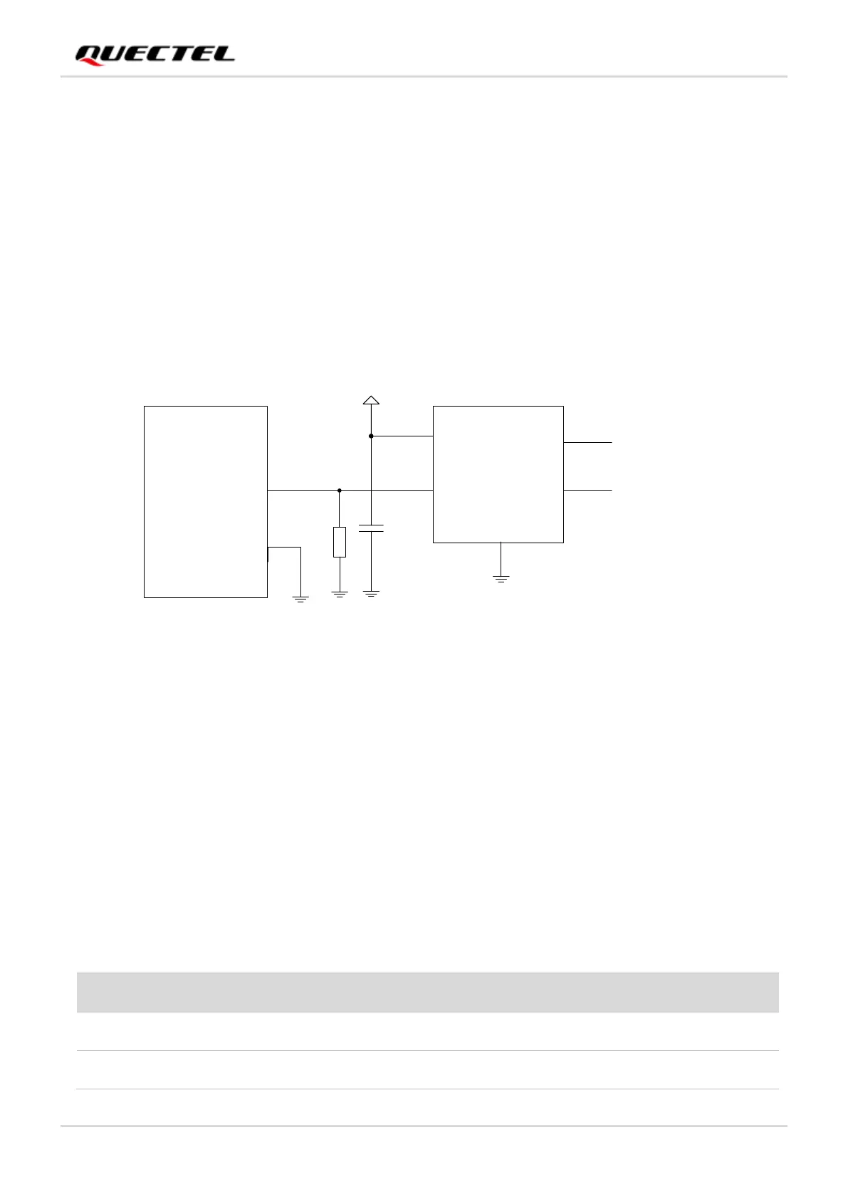
You can design an external backlight drive circuit for LCM according to actual requirement. PWM can be
used for backlight brightness adjustment.
Figure 20: Reference Design of LCM Interface External Backlight Drive
For more details about the principles when designing LCM interfaces, see Chapter 4.11.1.
4.11. Camera Interface
Based on MIPI CSI standard, the module supports 1 camera (4-lane) or 2 cameras (2-lane + 2-lane). The
maximum pixel of the camera is up to 8 MP. The video and photo quality are determined by various
factors such as the camera sensor, camera lens specifications, etc.
Table 27: Pins Description of Camera Interface
 Loading...


