Connecting power to the IDU Chapter 3
RADWIN 1000/2000/5000 User ManualVersion 2.5.30p3 3-11
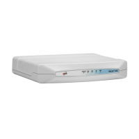
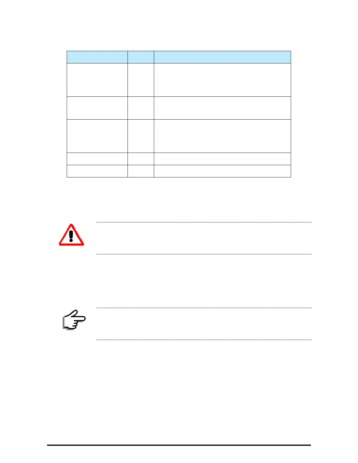
The purpose of the LEDs is shown in table 3-2 below:
To mount an IDU (using figure 3-8 above):
1. If the rack already holds other equipment, ensure that it is properly
grounded.
2. Attach the rack mounting brackets (K) to the IDU.
3. Bolt the IDU into an empty slot in the rack, ensuring that it sits securely.
4. Ground the IDU to the rack using grounding lug I. The IDU should be left
permanently grounded.
Connecting power to the IDU
The IDU-C has redundant power connection circuits (items G and H in
figure 3-8 above). An enlarged schematic of the power connectors is
shown in below:
Table 3-2: IDU-C Front Panel LEDs
Name Color Function
IDU Green
Green
Red
IDU operational
During power-up only
Failure
ODU Green
Red
ODU-to-IDU communication link is operating
ODU-to-IDU communication link is disrupted
AIR I/F Green
Orange
Red
Wireless link is synchronized
During installation mode only
Wireless link lost synchronization
SVC Off
HSS Off
Warning
Do not proceed with installation into a “live” rack unless it is properly
grounded.
Note
Instead of using the rack mounting brackets, the IDU may be rail mounted
using the four screw holes on each of its sides.
 Loading...