RADWIN2000UserManual Release2.8.30 B‐3
IDU(allmodels)AlarmConnector
IDU(allmodels)AlarmConnector
TheIDUAlarminterfaceisa25pinDtypefemaleconnector.ItspinoutislistedinTableB‐6.
Thefigurebelow,showshowtoconnectexternalinput andoutput alarms.
Ground 3 3
Ground 4 4
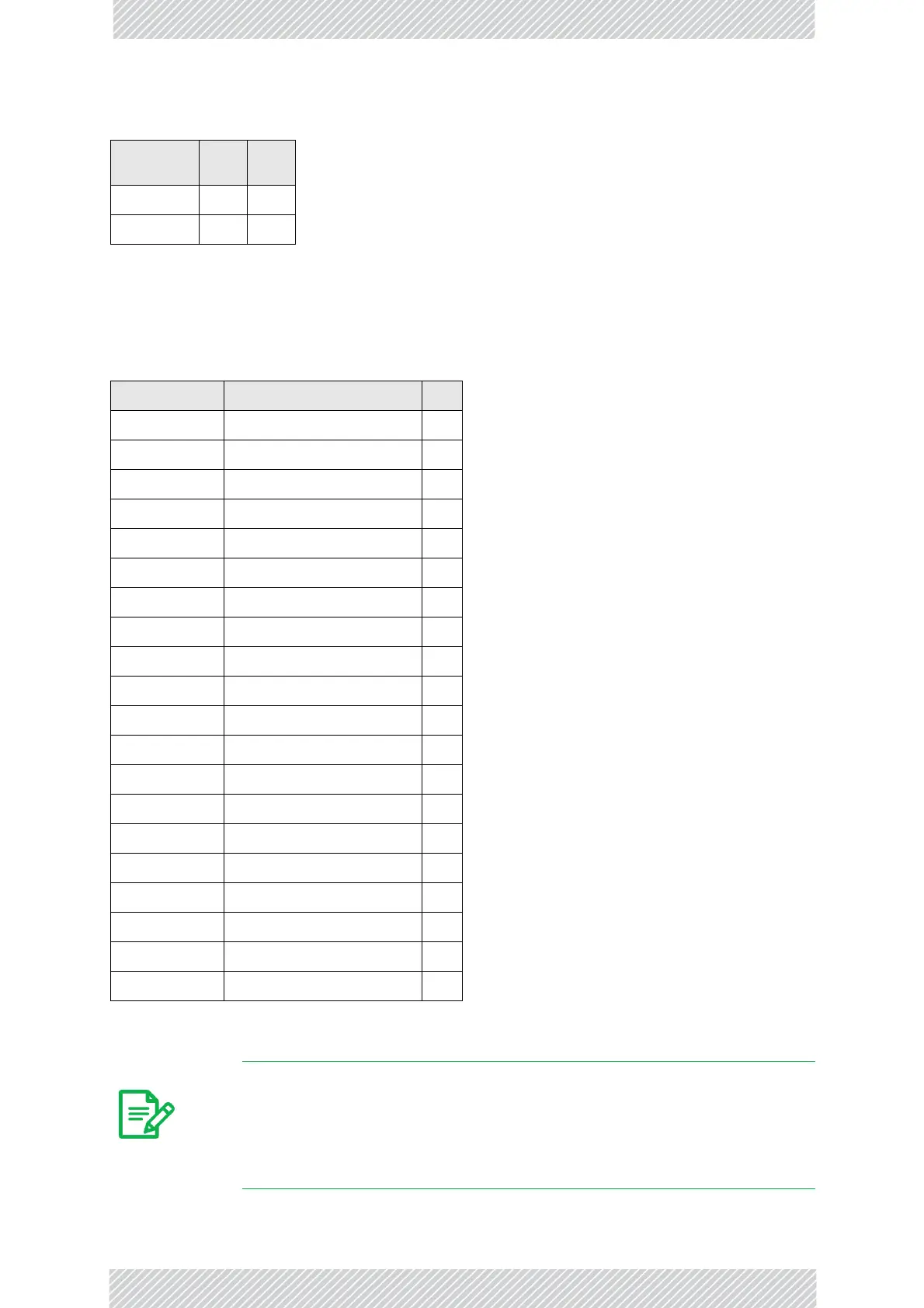
TableB‐6:IDU Alarm Connector (Dry-Contact)
I/O Description Pin
Input1 Positive 14
Input1 Negative 15
Input2 Positive 16
Input2 Negative 17
Input3 Positive 18
Input3 Negative 19
Input4 Positive 20
Input4 Negative 21
Output1 NormallyOpen 1
Output1 Common 2
Output1 NormallyClosed 3
Output2 NormallyOpen 4
Output2 Common 5
Output2 NormallyClosed 6
Output3 NormallyOpen 7
Output3 Common 8
Output3 NormallyClosed 9
Output4 NormallyOpen 10
Output4 Common 11
Output4 NormallyClosed 12
Note
• Useanexternalcurrentlimitresistortolimitthecurrentattheoutput
relaysto1Amp.Suchresistorisnotrequirediftheequipmentcon‐
nectedtotheIDUsupportscurrentlimitingto1Amp.
• Thevoltageoftheinputalarmmustbewithintherangeof‐10to‐50
VDC.
TableB‐5:Hot Standby RJ-11 Port Pinout (Continued)
Signal
Pin
SideA
Pin
SideB
 Loading...