74 RC435 and RC435i Chartplotters
The graphical XTE indication places arrows either side of the steering
instruction and pointing towards it, dependent on the value of XTE.
The first arrow is shown when the XTE reaches 0.01nm, the second
at.05nm and subsequently at 0.1nm intervals.
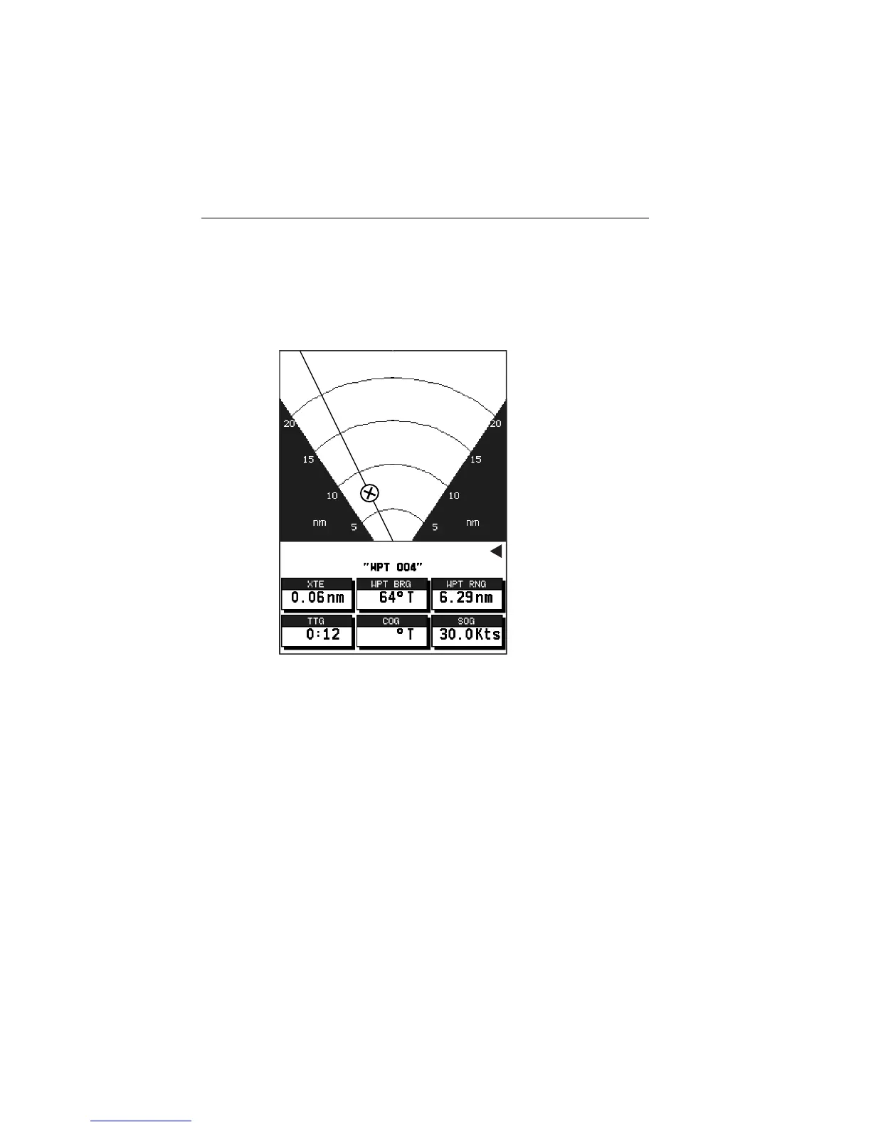
BDI Display
Figure 5-6: BDI Display
The BDI display shows deviation from the bearing to waypoint and
distance to waypoint. Cross track Error, Bearing to Waypoint, Distance to
Waypoint, Time to Go, CO G and SOG are also shown. Time To Go is
calculated on the basis of distance to destination and velocity made good
towards destination.
The line to the waypoint symbol is shown at an angle equal to the
difference between the COG and the Bearing to Waypoint.
The range scale automatically scales for distance. The ranges shown are
1nm, 4nm, 20nm, 40nm, 100nm, 200nm, 400nm, 1000nm, 2000nm,
4000nm. In each case the range scale has graduations at ¼, ½ and ¾ of the
current scale.
STEER PORT
76
D6242-2
 Loading...