15
eRev. [Major Version]1.01.0 8/9/2023
KrosFlo® KR2i Real-Time Process Management (RPM™) System
7. Setup and Operation
7.1 Basic Setup
Note: See Sections 7.2 through 7.7 for Sample Applications.
1. Mount the TFF system on a flat, horizontal surface with no more than two Pump Heads attached (see section 8.3 for Pump
Head Setup details).
2. Connect both Octopus Cables to the back of the TFF system.
3. Connect up to three pressure transducers to the Pressure Transducer Octopus Cable ports, depending on the application.
4. Connect an Automatic Backpressure Valves (ABV's) to the Auxiliary Component Octopus Cable "Valve" (see section 10.3 for
ABV Setup details).
5. Connect the FlowVPX to process tubing in between the feed reservoir and the KR2i pump. (See Section 9 FlowVPX setup
details.)
6. Connect power cable to the TFF system.
7. Follow guidelines and diagrams in sections 7.2 through 7.7 to determine which Auxiliary Components are required to
operate specific Process Modes for manual, semi-automated, and automated processes.
8. If using Auxiliary Pump, configure Auxiliary Pump before starting application (see section 10.2 for Auxiliary Pump Setup
details).
9. After connecting Auxiliary Components, power on the TFF system first before powering on Auxiliary Components.
10. Connect TFF flow path to TFF system.
11. Set low and high pressure alarms and interlocks as required by the process conditions.
12. Input Concentration Factor/Diafiltration Volume (CF/DV) set-points into the TFF system’s Process Mode settings to start
application.
Note: Valves, cables, and the computer are intentionally left out of the diagrams below for visual clarity.
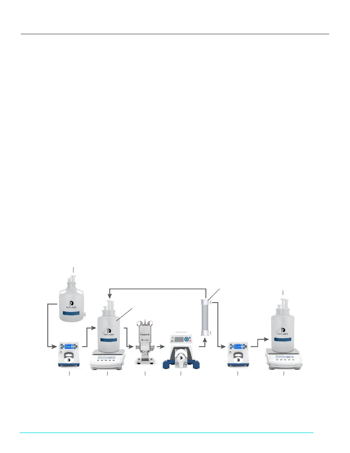
7.2 Manual Mode Setup
Figure 1. Manual Mode setup configuration
Diafiltration Pump
(Auxiliary Pump 1)
Permeate Pump
(Auxiliary Pump 2)
Diafiltration Buffer Reservoir

 Loading...


