39
eRev. [Major Version]1.01.0 8/9/2023
KrosFlo® KR2i Real-Time Process Management (RPM™) System
b. Set-point: What pressure set-point the Valve will attempt to reach and maintain
c. Tubing Size: Used to determine pinch distance
d. Control: Set whether Valve is controlling Feed, Permeate, Retentate, or TMP pressure
e. Start Position: The initial Start position before adjusting pinch distance:
• Open: no pinching
• Half: 50% closed based on tubing size
• Closed: 100% closed based on tubing size
• Custom: user defined
Manual Mode Menu
a. Mode: Can be set to Manual or Auto-- if set to Auto, settings will switch to Auto Mode Menu
b. % Closed: % of opening closed by pinch
c. Tubing Size: Determines pinch distance
10.4 KONDUiT
10.4.1 System Configuration
The base unit of KONDUiT integrates Conductivity, Temperature, and UV monitoring and automation functionalities into the TFF
System. There are 2 combination Conductivity and Temperature inputs (Cond/Temp), 2 UV inputs, and one power supply port.
Single-use Conductivity/Temperature Flowpath Components
Combination Conductivity and Temperature in-line flowpath sensors; made of Polysulfone and in assorted hosebarb sizes.
Optional: UV Photometer
Available in either 260 nm or 280 nm models; consists of 2 fiber optic cables, 2 optical couplers to connect to flow cell, and power
supply.
Note: UV Photometer cannot be remotely tared; to tare UV Photometer, press “TARE” button on Photometer body.
Optional: Single-use UV Flow Path Components
UV in-line flow path sensors; made of Polysulfone and in assorted hosebarb sizes.
10.4.2 Basic Setup
Note: Prior to assembling KONDUiT, ensure that TFF System has been properly set-up (see Section 7).
1. With TFF System powered on, connect KONDUiT Communication Cable to Auxiliary Octopus Cable.
2. Connect KONDUiT Power Cable to KONDUiT Power Port.
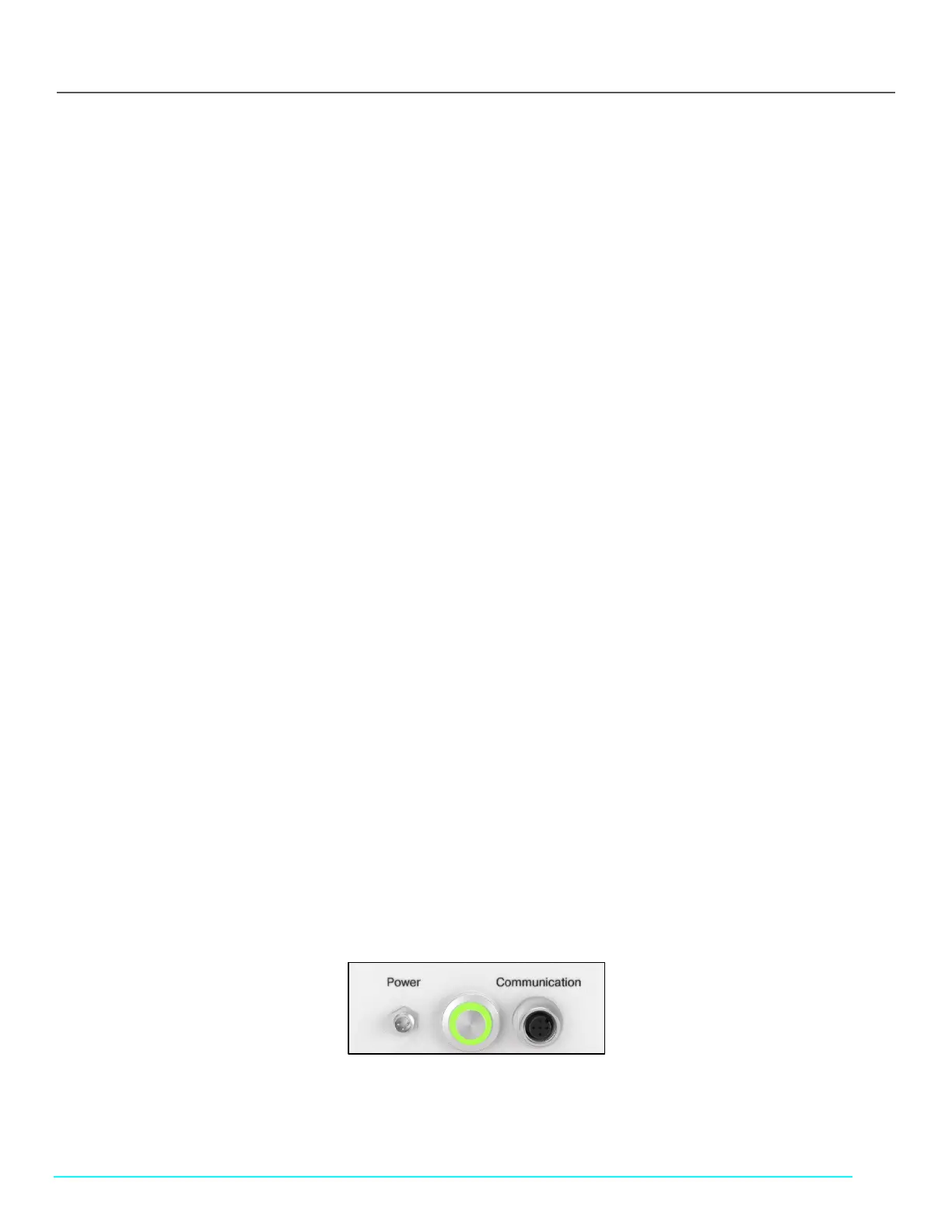
• On back of KONDUiT, green power light on the On/Off button indicates if KONDUiT is receiving power.
Figure 38. Back of KONDUiT, Green Power Indicator Light

 Loading...


