21
eRev. [Major Version]1.01.0 8/9/2023
KrosFlo® KR2i Real-Time Process Management (RPM™) System
8. Pump Head Setup and Operation
8.1 Introduction
The Easy-Load and High-Performance Pump Heads are designed to be used with the TFF systems as a simple peristaltic pump
system. The Pump Heads accept different tubing sizes for a wide range of flow rates, and the unique designs and automatic tubing
retention allow for quick tubing changes.
8.2 Tubing Specifications
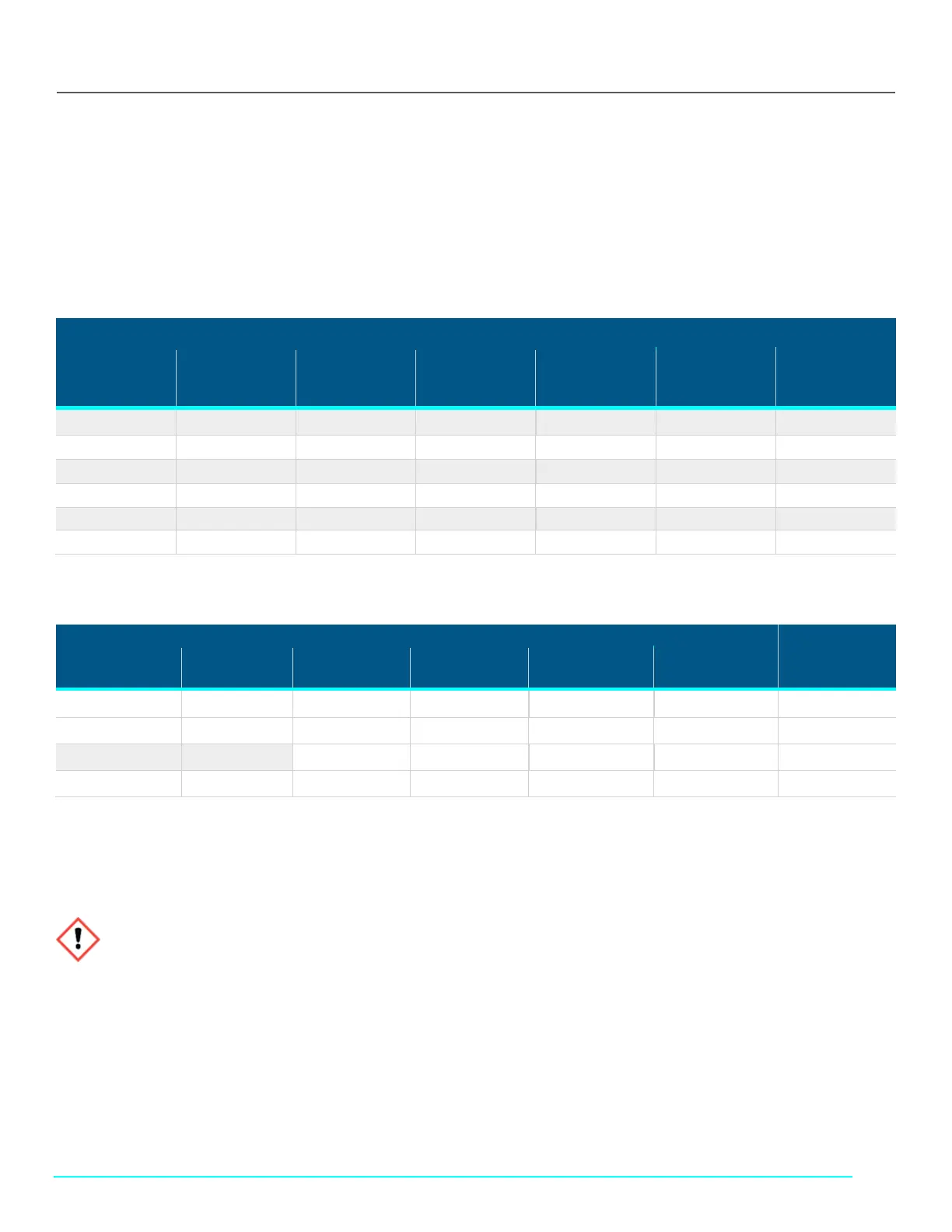
Table 12. ACR2-H3I-01N Typical Flow, Pressure, and Vacuum Data – 3 roller pumps
MasterFlex®
L/S® Tubing
Flow Rate* Discharge Pressure*
Vacuum*
@ 600 rpm
in (mm) Hg
Suction Lift*
@ 600 rpm
ft (m) H
2
O
@ 1 rpm
mL/rev
@ 600 rpm
mL/min
Continuous
psig (bar)
Inttermittent
psig (bar)
L/S® 13 0.06 36 25 (1.7) 40 (2.7) 26 (660) 29 (8.8)
L/S® 14 0.22 130 25 (1.7) 40 (2.7) 26 (660) 29 (8.8)
L/S® 16 0.8 480 25 (1.7) 40 (2.7) 26 (660) 29 (8.8)
L/S® 25 1.7 1000 20 (1.4) 35 (2.4) 26 (660) 29 (8.8)
L/S® 17 2.8 1700 15 (1.0) 20 (1.4) 20 (510) 22 (6.7)
L/S® 18 3.8 2300 10 (0.7) 15 (1.0) 20 (510) 22 (6.7)
Table 13. ACR2-H4I-01N Typical Flow, Pressure, and Vacuum Data – 3 roller pumps
MasterFlex®
L/S® Tubing
@ 600 rpm
@ 600 rpm ft
@ 600 rpm
Continuous psig
Intermittent psig
L/S® 15 1.7 1000 25 (1.7) 30 (2.7) 26 (660) 29 (8.8)
L/S® 24 2.8 1700 25 (1.7) 30 (2.7) 26 (660) 29 (8.8)
L/S® 35 3.8 2300 20 (1.4) 25 (2.4) 26 (660) 29(8.8)
L/S® 36 4.8 2900 15 (1.0) 20 (1.4) 24 (610) 27 (8.3)
*Specifications are valid for NORPRENE®, PHARMED®, and TYGON® tubing. Values will be less with silicone, C-FLEX®, and Viton®. Flow rate and
discharge pressure will vary based on tubing size, formulation, and operating temperature. The tables above are only a guide.
8.3 KR2i Installation and Removal
1. If mounting plate is not attached to the pump drive, attach it using the provided four Phillips head screws (see Figure 7).
WARNING: Stop the pump drive before installing or removing the pump head from the drive.

 Loading...


