32
eRev. [Major Version]1.01.0 8/9/2023
KrosFlo® KR2i Real-Time Process Management (RPM™) System
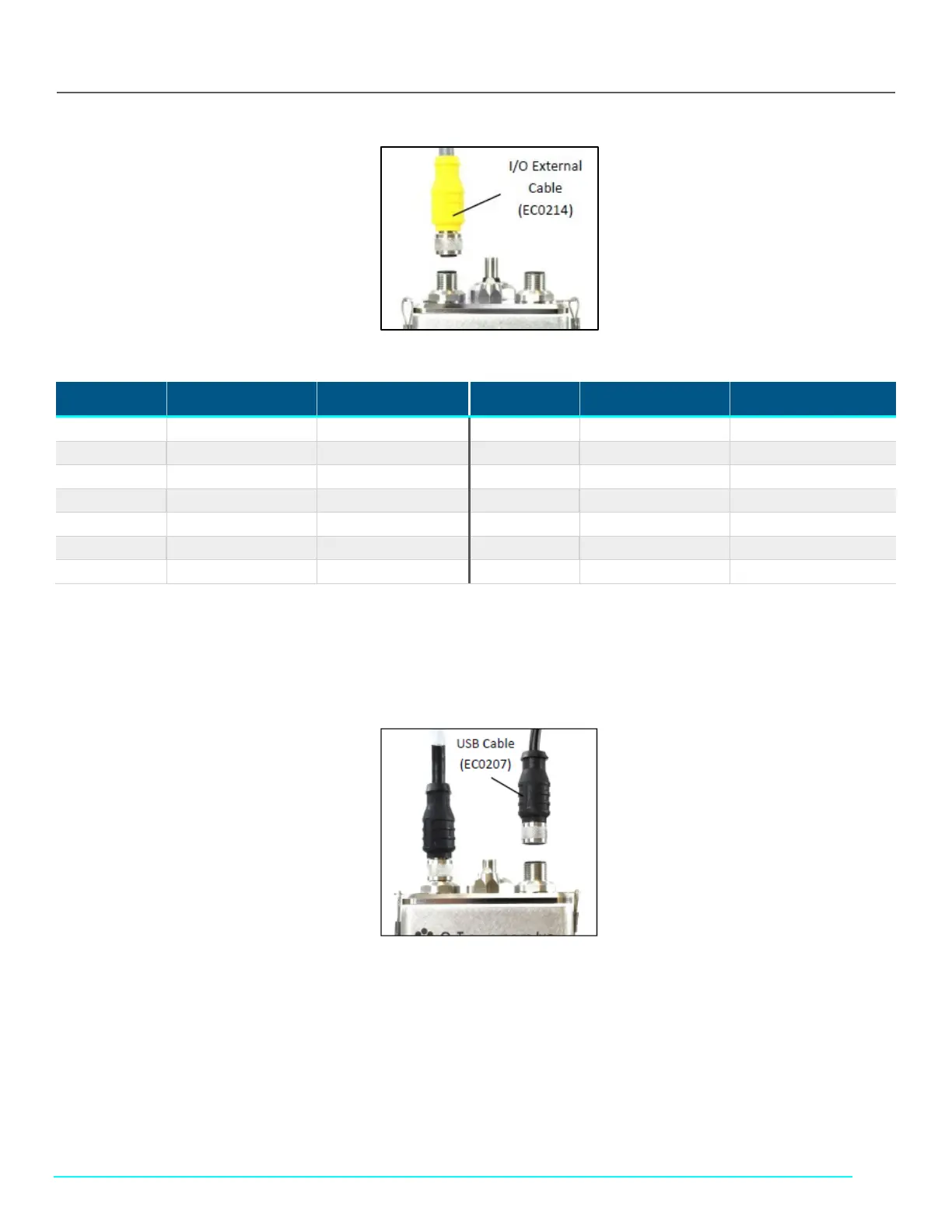
Figure 33. I/O External Cable (EC0214) to FlowVPX Head
Table 14. ACR2-H4I-01N Typical Flow, Pressure, and Vacuum Data – 3 roller pumps
Pin No. Wire Color Function Pin No. Wire Color Function
1 White NC*/+24 VDC 7 Blue Digital Out 0
2 Brown NC*/0 VDC** 8 Red Digital Out 1
3 Green DIO Common 9 Orange Digital Out 2
4 Yellow Digital In 0 10 Tan Analog Ground
5 Gray Digital In 1 11 Black Analog Out 1
6 Pink Digital In 2 12 Violet Analog Out 2
- Bare Ground
*With Power Supply (EC0205) and Power/IO Splitter (EC0208).
**User provided power (24 VDC, 120 W), direct connection to the FlowVPX Head.
Note: If providing a 24 VDC power source, connect the I/O External Cable (EC0214) directly to the Power and I/O labeled connector on
the top of the FlowVPX® Head.
Figure 34. USB Cable (EC0207) to FlowVPX Head
9. Connect the USB cable (EC0207) to the USB communications connector on top of the FlowVPX® Head.
10. Connect the FlowVPX USB cable (EC0207) to a USB port on the computer (Figure 36). Make sure the computer is turned on.

 Loading...


