IF.UG.IM_R1
Table 4. KrosFlo® System Electrical Specifications
Note:
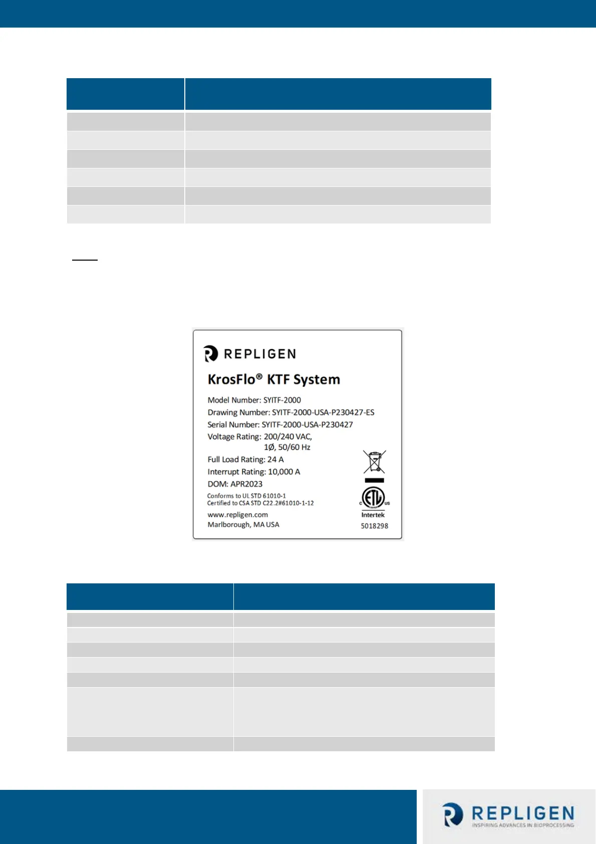
Below is a sample System machine designation label, located on the back side of the controller
cabinet. Observe all listed electrical ratings and ensure those are met before using the System.
Figure 1. Sample Machine Designation Label
Table 5. KrosFlo® System Environmental Specifications
KrosFlo® System Model Power Utility Required
200-240 VAC (±10%), 1Ph (Neutral and Ground), 50/60 Hz, 20A
200-240 VAC (±10%), 1Ph (Neutral and Ground), 50/60 Hz, 20A
200-240 VAC (±10%), 1Ph (Neutral and Ground), 50/60 Hz, 20A
200-240 VAC (±10%), 1Ph (Neutral and Ground), 50/60 Hz, 30A
200-240 VAC (±10%), 1Ph (Neutral and Ground), 50/60 Hz, 30A
200-240 VAC (±10%), 1Ph (Neutral and Ground), 50/60 Hz, 30A
KrosFlo® System Specification
300 lbs./135 Kg (approximately)
Frame and Controller Cabinet: SS-304
Casters: SS-304 and Polyurethane
Flow-path Components: Polypropylene, polycarbonate,
Polysulfone, and C-Flex/Pharmapure materials

 Loading...


